High-power LED driver

A LED driver and high-power technology, which is applied in the field of high-power light-emitting diode drivers, can solve the problems of limiting dimming ratio and dimming frequency, switching signal and dimming signal asynchronous, etc., and achieve the effect of reducing manufacturing costs

Inactive Publication Date: 2009-11-11
ZHEJIANG UNIV
View PDF0 Cites 16 Cited by
  • Summary
  • Abstract
  • Description
  • Claims
  • Application Information

AI Technical Summary

Problems solved by technology

[0005] But this dimming method has disadvantages, such as Figure 4 As shown, firstly, when the PWM dimming signal control is “on”, if the peak current control is adopted, affected by the control loop, the LED current needs to go through several switching cycles (that is, the signal cycle for controlling the power switch tube) to reach the rated current value; Secondly, the switching signal is not synchronized with the PWM dimming signal
Due to the existence of the above two problems, the minimum "on time" of the PWM dimming signal is 3-5 switching cycles, which limits the dimming ratio and dimming frequency

Method used


Image

  • High-power LED driver
  • High-power LED driver
  • High-power LED driver

Examples


Embodiment Construction

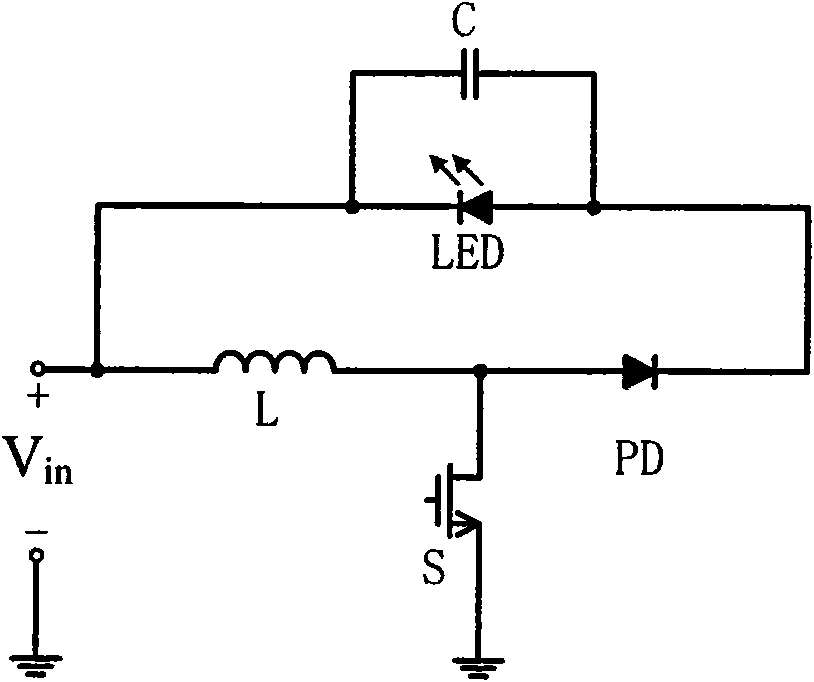
[0026] A high-power LED driver of the present invention, such as Figure 5 Shown, including:

[0027] A buck-boost switching converter including an inductor L: used to convert the input voltage into a suitable LED drive voltage; the buck-boost switching converter uses the first and second extremes of the inductor L as output terminals, and the switching is converted The first terminal of the inductor L is connected to the cathode of the light emitting diode LED, and the second terminal is connected to the anode of the light emitting diode LED. The first terminal of the inductance L is used to connect a voltage signal, that is, the voltage source V between the first terminal of the inductance L and the ground terminal in , Used to provide input voltage.

[0028] Current detector: used to detect the current value of the inductor L in the switching converter and provide the detected current value to the controller.

[0029] Controller: According to the current value detected by the c...


PUM


Abstract

The invention discloses a high-power LED driver comprising a boost-buck switching converter which takes a first pole terminal and a second pole terminal of an inductor as output ends, a current detector for detecting current value of the inductor in the switching converter and a controller for receiving a signal of the current detector. A cycle control circuit is arranged in the boost-buck switching converter for receiving a control signal of the controller to maintain the current of the inductor within a certain threshold; the cycle control circuit comprises a first power switch tube which is connected between the second pole terminal of the inductor and a ground terminal and a second power switch tube which is connected between the first pole terminal and the second pole terminal; and the controller comprises a first control terminal and a second control terminal for respectively controlling the first power switch tube and the second power switch tube to turn on and turn off. Compared with the traditional driver, the LED driver reduces a power element and can provide stable current for an LED and achieve a higher dimming ratio than the traditional structure by being matched with the corresponding control strategy.

Description

Technical field [0001] The present invention relates to the field of power electronics design, in particular to a high-power light emitting diode (LED) driver. Background technique [0002] White LED is called "the new light source of the 21st century" because of its outstanding advantages such as long life and energy saving. In addition, due to its three-wavelength full color and high lumen characteristics, it is very suitable for use as a display backlight. [0003] In order to make the LED work efficiently and stably, a dedicated drive controller must provide power for it. Due to the characteristics of LEDs, current LED drivers usually use current control, that is, maintaining stable brightness and color by constant average current flowing through the LED. Therefore, the overall development trend of LED drivers is: to further improve the conversion efficiency and output power under the premise of ensuring the accuracy of output current control; reduce the number of external co...

Claims


Application Information

Patent Timeline
Patent Type & Authority Applications(China)
IPC IPC(8): H05B37/02
Inventor 孙越明吴晓波赵梦恋
Owner ZHEJIANG UNIV
Why Eureka
Try Eureka