Devices and methods for leaflet cutting

Pending Publication Date: 2021-11-11
EVALVE
View PDF7 Cites 1 Cited by
  • Summary
  • Abstract
  • Description
  • Claims
  • Application Information

AI Technical Summary

Benefits of technology

The present invention solves problems in the art by providing a system for cutting leaflet tissue at a cardiac valve. The system includes a guide catheter with a distal end capable of being positioned above a cardiac valve, and a cutting mechanism routable through the guide catheter. The method involves placing the cutting mechanism into contact with leaflet tissue adjacent to an interventional implant and actuating the cutting mechanism to cut at a portion of at least one leaflet. The technical effect of this invention is the ability to safely and effectively cut leaflet tissue to facilitate the placement of interventional implants.

Problems solved by technology

However, in some circumstances the mitral valve is unable to close properly, allowing blood to regurgitate back into the atrium.
The need to both, open the chest, and place the patient on bypass, is traumatic and has an associated high mortality and morbidity rate.
However, sometimes after a fixation device is installed, undesirable mitral valve regurgitation can still exist, or can arise again.
For patients requiring re-intervention, the presence of a fixation device in their mitral valves obstructs transcatheter mitral valve replacement.
These patients may also be considered too frail to tolerate open-heart surgery, so they are left with no viable options to further improve the function of their mitral valve.

Method used


Image

  • Devices and methods for leaflet cutting
  • Devices and methods for leaflet cutting
  • Devices and methods for leaflet cutting

Examples


first embodiment

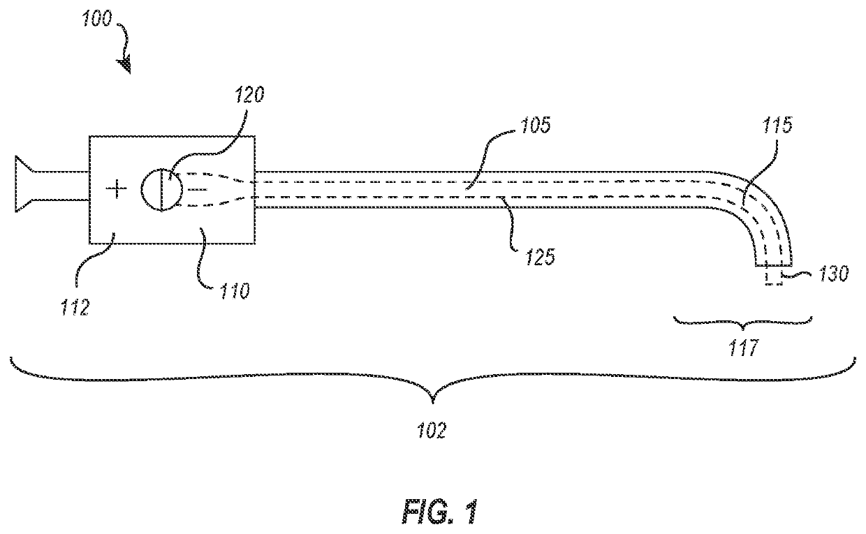
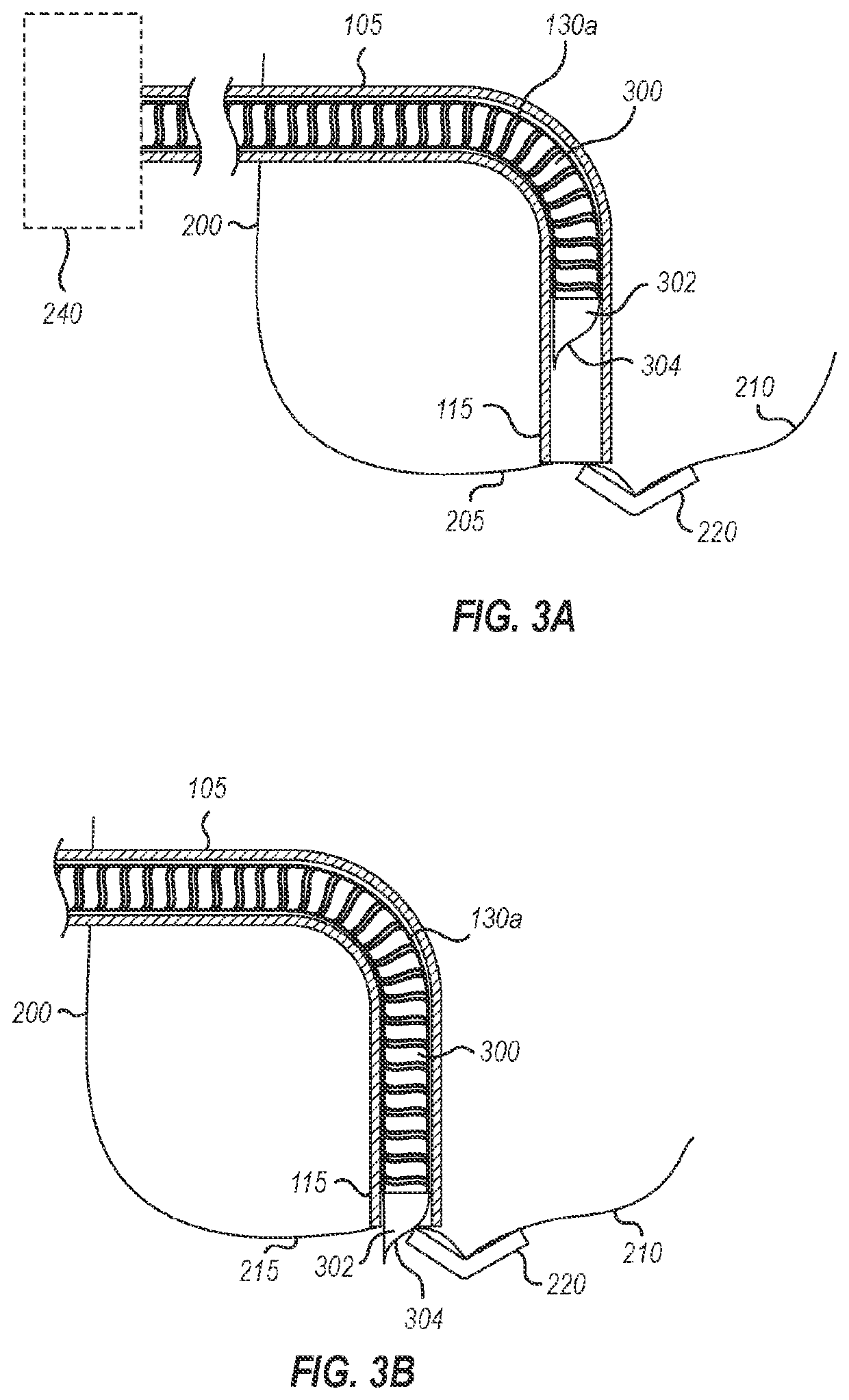
[0037]Referring next to FIGS. 3A-3D, which illustrate a leaflet cutting system 100. System 100 includes components corresponding to those described above in connection with FIG. 1, which are designated by the same reference numerals throughout. As shown in FIGS. 3A-3D, system 100 also includes a cutting mechanism 130a positioned within, and routed through, the guide catheter 105. As shown, the cutting mechanism 130a may comprise an elongate inner catheter or hypotube 300, extending from a proximal end (not shown in FIG. 3) to a distal end 302 of the leaflet cutting system 100. The proximal end of the cutting mechanism 130a can be operatively coupled to the handle 110, and handle 110 provided with controls adapted to manipulate the cutting catheter 130a, including advancing, retracting and / or rotating the cutting mechanism 130a relative to the guide catheter 105.

[0038]As shown in FIG. 3A, cutting mechanism 130a is positioned within the interior of guide catheter 105 during advancemen...

second embodiment

[0045]Reference is next made to FIGS. 4A-4F, which illustrate a cutting mechanism 130b. This embodiment also includes components corresponding to those described above in connection with FIG. 1, which are designated by the same reference numerals throughout. FIG. 4A is a side sectional view of the cutting mechanism 130b shown within the distal end 115 of the guide catheter 105. As shown, the cutting mechanism 130b may comprise an inner catheter or hypotube 400 having a sharpened, cutting end 402, which terminates at its distal end in a sharpened point. This embodiment, the sharpened cutting end 402 can include two blades 404 and 406 joined at a pivot point. The two blades 404 and 406 may each comprise a cutting edge disposed on an outer edge of each blade as illustrated in FIG. 4B. The hypotube 400 may be configured to be selectively extended from the distal end 115 of the guide catheter 105, thereby allowing the two blades 404 and 406 to engage with a portion of leaflet tissue.

[004...

embodiment 1

[0073] A system for cutting leaflet tissue at a cardiac valve, comprising a guide catheter having a proximal end and a distal end, wherein the distal end of the guide catheter is steerable to a position above a cardiac valve, a handle coupled to the proximal end of the guide catheter, the handle comprising at least one control configured to steer the guide catheter to the position above the cardiac valve, and a cutting mechanism routable through the guide catheter and able to be positioned at the distal end of the guide catheter, the cutting mechanism configured to cut a portion of leaflet tissue of the cardiac valve.

[0074]Embodiment 2. The system of embodiment 1, wherein the at least one control is further configured to provide selective actuation of the cutting mechanism.

[0075]Embodiment 3. The system in any of embodiments 1 to 2, wherein the guide catheter is introduced transseptally.

[0076]Embodiment 4. The system in any of embodiments 1 to 3, further comprising an indeflator att...


PUM


Abstract

A system for cutting leaflet tissue at a cardiac valve may comprise a guide catheter having a proximal end and a distal end, wherein the distal end of the guide catheter is steerable to a position above a cardiac valve. The system may also include a handle coupled to the proximal end of the guide catheter, the handle comprising at least one control configured to steer the guide catheter to the position above the cardiac valve. Finally, the system may comprise a cutting mechanism routable through the guide catheter and able to be positioned at the distal end of the guide catheter, the cutting mechanism configured to cut a portion of leaflet tissue of the cardiac valve.

Description

CROSS-REFERENCE TO RELATED APPLICATIONS[0001]This application claims priority to U.S. Provisional Patent Application No. 63 / 020,669, filed May 6, 2020, the entire contents of which are incorporated by reference herein.BACKGROUND OF THE INVENTION[0002]The mitral valve controls blood flow from the left atrium to the left ventricle of the heart, preventing blood from flowing backwards from the left ventricle into the left atrium so that it is instead forced through the aortic valve for delivery of oxygenated blood throughout the body. A properly functioning mitral valve opens and closes to enable blood flow in one direction. However, in some circumstances the mitral valve is unable to close properly, allowing blood to regurgitate back into the atrium.[0003]Mitral valve regurgitation has several causes. Functional mitral valve regurgitation is characterized by structurally normal mitral valve leaflets that are nevertheless unable to properly coapt with one another to close properly due ...

Claims


Application Information

Patent Timeline
IPC IPC(8): A61B18/14
CPCA61B18/1442A61B2018/00369A61B18/1492A61B17/320016A61B2017/00243A61B2017/00783A61B2018/00291A61B2018/00601A61B2090/3966A61B18/1445A61B2018/1457A61B2018/1452A61B2018/0072
Inventor CHILDS, RICHARD THOMASMOSHER, SCOTT C.TROXLER HARVEY, LAURENKIZUKA, KOJI J.NAIR, AJITKUMAR B.KALVASS, LAURA M.
Owner EVALVE
Why Eureka
Try Eureka