Power switch device

a power switch and switch technology, applied in the direction of power supply for data processing, liquid/fluent solid measurement, instruments, etc., can solve the problems of high input current peak value, hardware damage and data loss, and the computer system often needs to be detected and repaired for normal operation, etc., to facilitate deployment and configuration of electric devices, simplify the composition of power management architecture, and facilitate the effect of adding quickly

Active Publication Date: 2021-11-11
GIGA BYTE TECH CO LTD +1
View PDF0 Cites 0 Cited by
  • Summary
  • Abstract
  • Description
  • Claims
  • Application Information

AI Technical Summary

Benefits of technology

[0028]In one or more embodiments of the instant disclosure, a plurality of power switch devices are sequentially turned on at an appropriate time interval (during a start process time period), so that each corresponding electric device can be turned on sequentially not simultaneously. Therefore, the power switch device of the instant disclosure can prevent the instantaneous output current of the power supply system from exceeding the upper current load limit, thereby preventing the power supply system from performing overcurrent shutoff protection. The plurality of power switch devices are turned on through collaborative operation, so that there is no need to dispose a centralized management device additionally, which can simplify the composition of a power management architecture. In addition, the power switch device can be quickly added to or removed from an existing group of power switch devices, which facilitates deployment and configuration of the electric device.

Problems solved by technology

When an electric device is started after powered on, an input current of the electric device is subject to a surge, resulting in a high peak value of the input current.
A power failure either during start or during operation may cause hardware damage and data loss.
Therefore, after the overload power-off protection mechanism occurs, the computer system often needs to be detected and repaired for normal operation.

Method used


Image

  • Power switch device
  • Power switch device
  • Power switch device

Examples


first embodiment

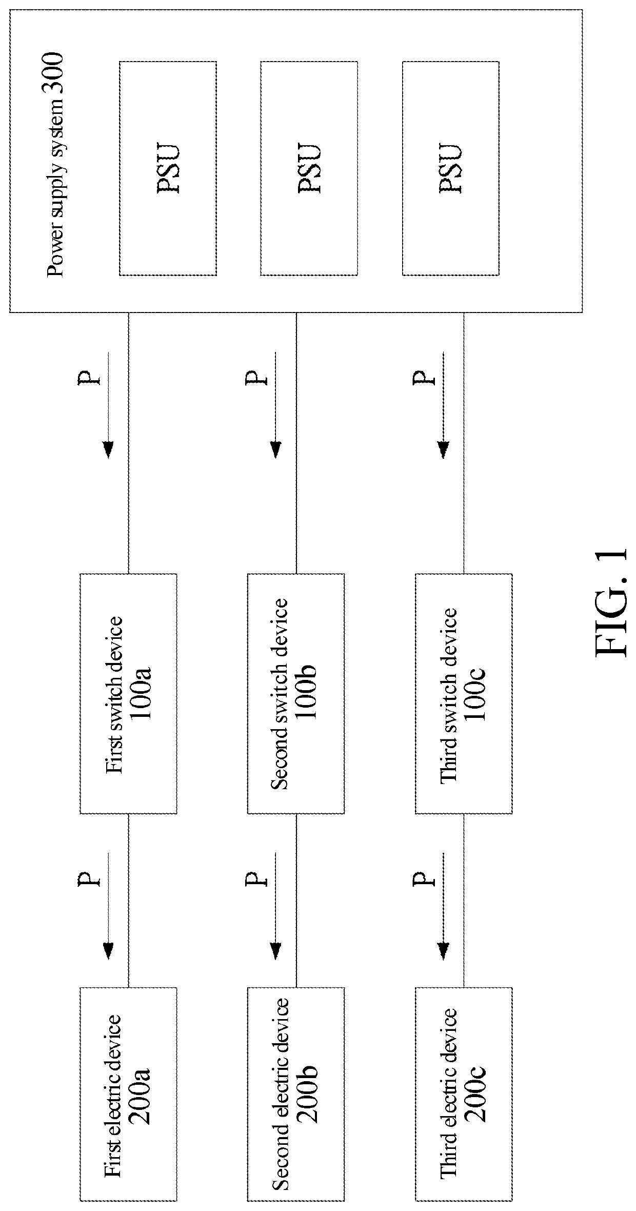
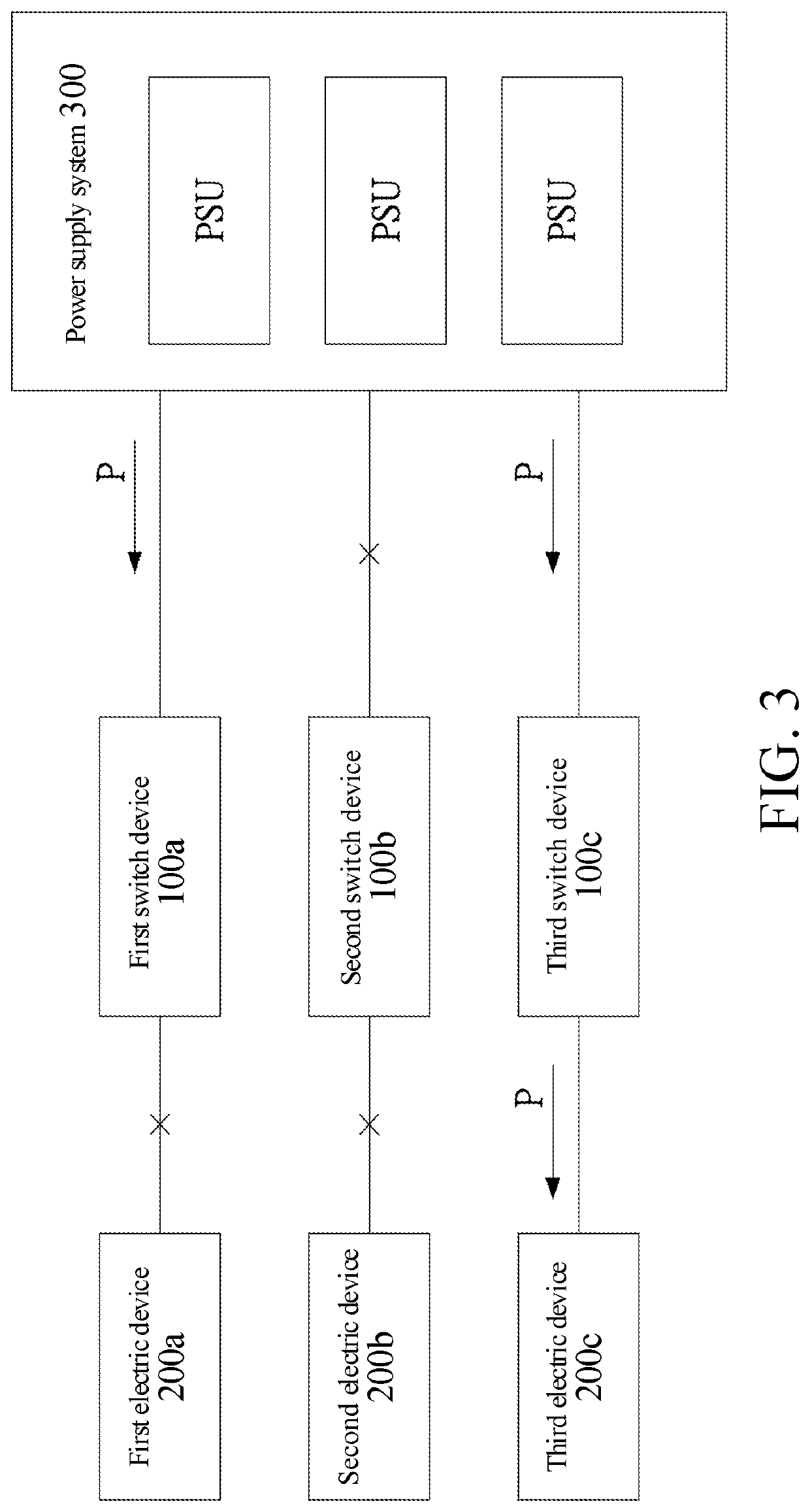
[0044]As shown in FIG. 1, a power switch device 100a, 100b, 100c disclosed in the instant disclosure is electrically connected to a power supply system 300. The power switch device 100a, 100b, 100c is electrically connected to an electric device 200a, 200b, 200c, respectively. Power outputted by the power supply system 300 is transmitted to the electric device 200a, 200b, 200c via the power switch device 100a, 100b, 100c. After receiving power via the power switch device 100a, 100b, 100c, the electric device 200a, 200b, 200c may start to perform a start process to be in an available state. The power supply system 300 may be a single power supply unit PSU, or may be a power array composed of two or more PSUs, or may be a power system in a building. For clarity, the power switch device 100a, 100b, 100c is divided into a first switch device 100a, a second switch device 100b, and a third switch device 100c, and the electric device 200a, 200b, 200c is divided into a first electric device...

second embodiment

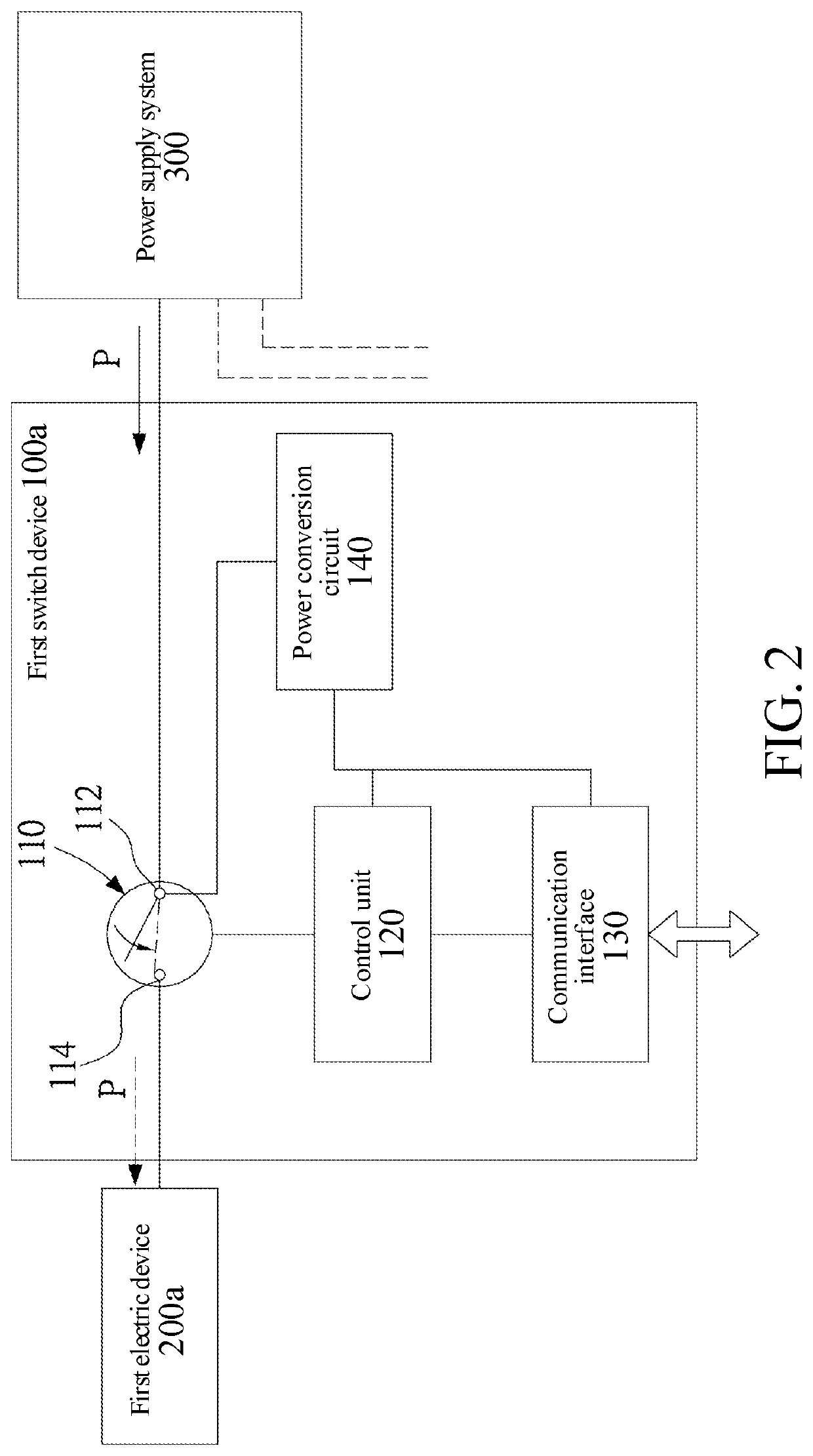
[0062]FIG. 9 and FIG. 10 show a power switch device 100a, 100b, 100c disclosed in the instant disclosure, which is electrically connected to a power supply system 300. The power switch device 100a, 100b, 100c is electrically connected to an electric device 200a, 200b, 200c, respectively. A circuit composition of the power switch device 100a, 100b, 100c is substantially the same as that shown in FIG. 2, and details are not described below.

[0063]Referring to FIG. 2, FIG. 9, and FIG. 10, in the second embodiment, the control unit 120 has a controlling operating mode and a controlled operating mode to switch the power switch device 100a, 100b, 100c to a controlling device or a controlled device. The first switch device 100a is used to describe the switching between the controlling operating mode and the controlled operating mode below. A message packet via the communication interface 130 may be transmitted in a manner of broadcasting. Therefore, the control unit 120 of the power switch ...


PUM


Abstract

A power switch device includes a switch, a control unit, and a communication interface. The switch includes a power input terminal, which is configured to receive an external power; and a power output terminal, which is configured to output the external power. The switch normally remains open. The control unit is turned on when receiving the external power via the power input terminal, and transmits a start request via the communication interface. The control unit determines whether the communication interface receives a busy message within a delay time period. If the busy message is not received within the delay time period, the control unit controls the switch to be closed, and sets a start process time period. Within the start process time period, if the communication interface receives another start request, the control unit generates another busy message to respond to the another start request via the communication interface.

Description

CROSS-REFERENCE TO RELATED APPLICATION[0001]This non-provisional application claims priority under 35 U.S.C. § 119(a) to Patent Application No. 109115270 filed in Taiwan, R.O.C. on May 7, 2020, the entire contents of which are hereby incorporated by reference.BACKGROUNDTechnical Field[0002]The instant disclosure relates to the start management of an electric device, and in particular, to a power switch device.Related Art[0003]When an electric device is started after powered on, an input current of the electric device is subject to a surge, resulting in a high peak value of the input current. In a computer system, a single power supply system is usually used to supply power to a plurality of electric devices. The above electric device may be a built-in device in a single computer host, or may be separate computer hosts, that is, even a plurality of computer hosts simultaneously supply power with a single power supply system.[0004]The electric device automatically starts when being po...

Claims


Application Information

Patent Timeline
Patent Type & Authority Applications(United States)
IPC IPC(8): G06F1/28G06F1/26
CPCG06F1/28H02J4/00G06F1/263G06F1/26
Inventor KAO, CHIN-JUN
Owner GIGA BYTE TECH CO LTD
Why Eureka
Try Eureka