
Apparatus and method for determining an indication of blood flow

a technology of blood flow and apparatus, applied in the field of apparatus and method for determining an indication of blood flow, can solve the problems of reducing the flow of blood through the vein, affecting the measurement and affecting the accuracy of venous drainage measurement,

Pending Publication Date: 2021-11-18
WHITMARSH TRISTAN +1
View PDF0 Cites 0 Cited by
  • Summary
  • Abstract
  • Description
  • Claims
  • Application Information

AI Technical Summary

Benefits of technology

The invention is an apparatus and method for determining the indication of blood flow in a limb by measuring the change in orientation of the limb and correlating it with the change in blood volume of the limb. This allows for the determination of an indication of venous drainage of the limb, which can be useful in diagnosing and treating medical conditions such as deep vein thrombosis. The apparatus includes an orientation sensor and a blood volume measuring device, such as a pressure cuff or an impedance measurement device, which can be attached to the limb or the torso. The method involves receiving the orientation signal and the BV signal, determining the change in orientation and blood volume, and optionally correcting the indication of blood flow based on predetermined criteria. The technical effect of the invention is to provide a reliable and non-invasive way to measure blood flow in a limb.

Problems solved by technology

With such problems, a blood clot impedes the flow of blood through the vein.
Reduced blood flow is difficult to measure in primary care settings, with doctors often relying on checklists of non-specific symptoms.
However, there are currently problems with measuring venous drainage in this way.
Firstly, the machinery to measure the blood volume changes is often bulky, expensive and not easily placed in a doctor's office.
Secondly, the interpretation of the resultant data is difficult and requires extensive prior experience.
Thirdly, irregular movement of the limb in patients with poor mobility complicates the interpretation of the resultant data, leading to inaccuracies.

Method used


Image

  • Apparatus and method for determining an indication of blood flow
  • Apparatus and method for determining an indication of blood flow
  • Apparatus and method for determining an indication of blood flow

Examples


Embodiment Construction

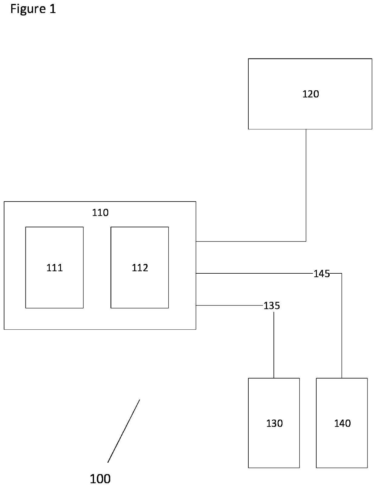
[0048]FIG. 1 shows a schematic illustration of an apparatus 100 according to an embodiment of the invention. Embodiments of the apparatus 100 may be used to determine an indication of blood flow in a limb, for example to determine an indication of venous drainage of a limb. Embodiments will be described where the limb is a leg of a subject, although it will be appreciated that this is merely illustrative. The apparatus 100 is envisaged to be suitable for use with other limbs, such as arms.

[0049]The illustrated embodiment of the apparatus 100 comprises a control unit 110, a user interface 120, an orientation sensor 130 and a blood volume measurement device 140.

[0050]The orientation sensor 130 is arranged to determine an orientation of the limb i.e. the leg. The orientation sensor 130 may be, in some embodiments, an accelerometer or a gyroscope, however the orientation sensor may be any device capable of measuring orientation of the limb. The orientation sensor 130 may be arranged as ...


PUM


Abstract

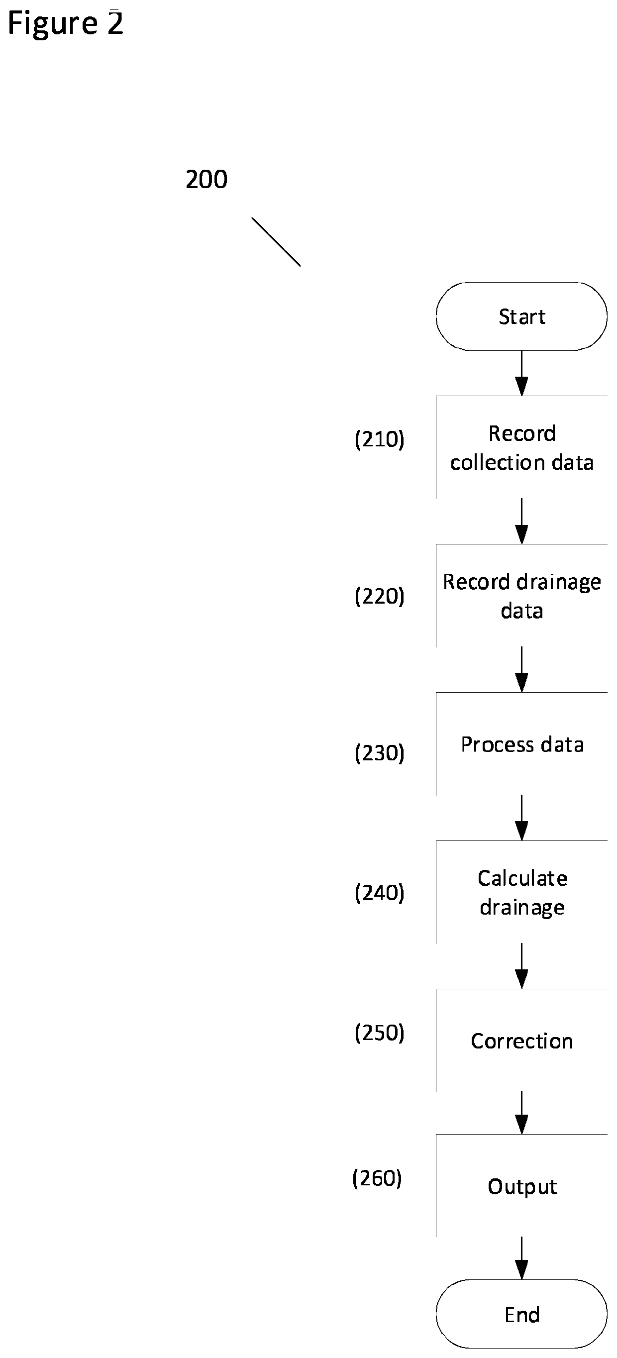
The present invention relates to an apparatus and a method for determining an indication of blood flow in a limb. According to an embodiment, the apparatus comprises an orientation sensor, a blood volume (BV) measuring device and a control unit. The orientation sensor is configured to determine an orientation of the limb and output an orientation signal indicative thereof. The blood volume measurement device is configured to measure an indication of blood volume (BV) in the limb and output a BV signal indicative thereof. The control unit is arranged to receive the orientation signal and the BV signal, determine a change in orientation of the limb in dependence on the orientation signal, and correlate the change in orientation with a change in blood volume of the limb determined in dependence on the BV signal.

Description

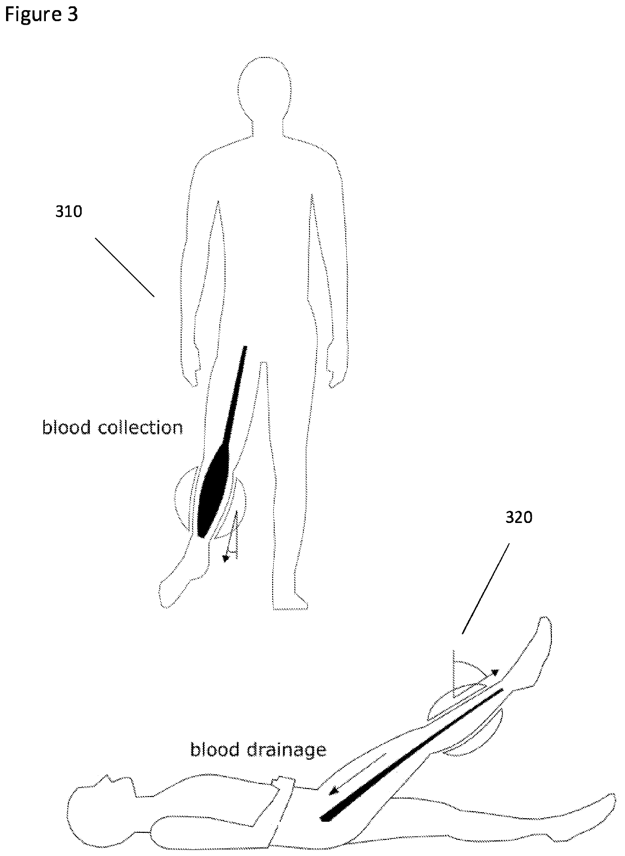
BACKGROUND[0001]Assessment of how well blood can flow through veins has many practical applications in healthcare, in particular the monitoring of a variety of circulatory problems including deep vein thrombosis (DVT). With such problems, a blood clot impedes the flow of blood through the vein. Blood clot detection relies on the accurate measurement of reduced blood flow. Reduced blood flow is difficult to measure in primary care settings, with doctors often relying on checklists of non-specific symptoms.[0002]One way to measure how well the blood flows though the vein is by measuring a venous drainage. Venous drainage can be quantified as a rate of flow out of a limb. For example, in a healthy subject laid in supine position, lifting their leg will cause the blood in the leg to quickly flow out of the veins of the leg. In contrast, in an occluded vein the blood will flow out slowly. The rate of venous drainage can be measured in millilitres per second. However, there are currently ...

Claims


Application Information

Patent Timeline
IPC IPC(8): A61B5/0295A61B5/00
CPCA61B5/0295A61B5/7246A61B2562/0261A61B2562/0219A61B2562/0257A61B5/02152A61B5/1116
Inventor WHITMARSH, TRISTANMILNER, PIERSELZEIN MOHAMED, AHMED
Owner WHITMARSH TRISTAN
Learn More