
Method and Compositions for Embedding Electronics in Fiber-Composite Parts Fabricated via Compression Molding

a technology of fiber-composite parts and additive molding, which is applied in the direction of printed circuit parts, printed circuit non-printed electric components association, other domestic articles, etc., can solve the problems of limited design latitude of molded parts, inability to locate electronic components, and inability to “embed” electronics. , to achieve the effect of increasing design latitud

Active Publication Date: 2021-11-18
ARRIS COMPOSITES INC
View PDF4 Cites 0 Cited by
  • Summary
  • Abstract
  • Description
  • Claims
  • Application Information

AI Technical Summary

Benefits of technology

The present invention allows for the precise placement of electronic components within a molded part's internal volume. By using fiber-based preforms, the placement of components can be more accurately and with greater precision than traditional methods. This results in better protection from external environmental stressors and improved part properties.

Problems solved by technology

Currently, technologies for fabricating molded parts are limited in terms of their ability to “embed” electronics; that is, there is an inability to locate an electronic component at an arbitrary location within the volume of a part.
The aforementioned limitation is due, at least in part, to the nature of the feedstock constituents or “charge” to the molding process.
Indeed, particulate charge is randomly oriented throughout the molding process, so any notion of particulate alignment / orientation / organization is meaningless.
As a consequence, a particulate-based charge itself cannot locate, index, or register embedded components, at least in a single-step molding process.
It will be appreciated that absent sufficient constraint, electrical components can become improperly located and / or spatially oriented in a final part.
Thus, it has been challenging or impossible to embed a component at a desired arbitrary location within a part's internal volume in a single-step molding process.

Method used


Image

  • Method and Compositions for Embedding Electronics in Fiber-Composite Parts Fabricated via Compression Molding
  • Method and Compositions for Embedding Electronics in Fiber-Composite Parts Fabricated via Compression Molding
  • Method and Compositions for Embedding Electronics in Fiber-Composite Parts Fabricated via Compression Molding

Examples


Embodiment Construction

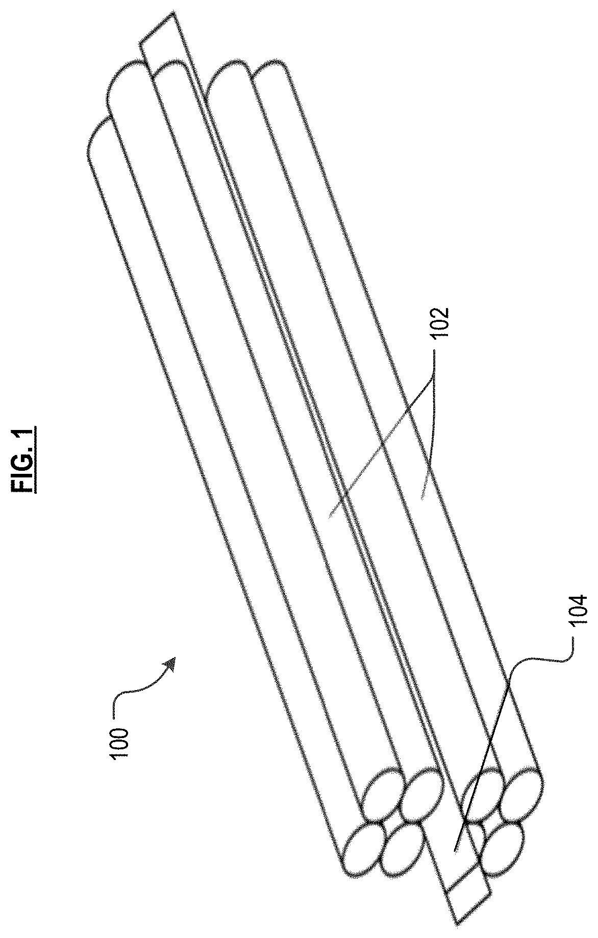
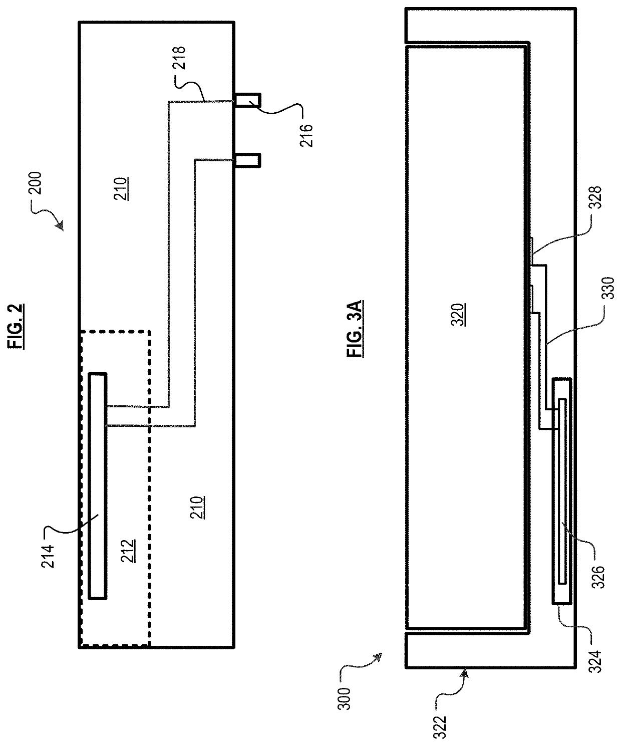
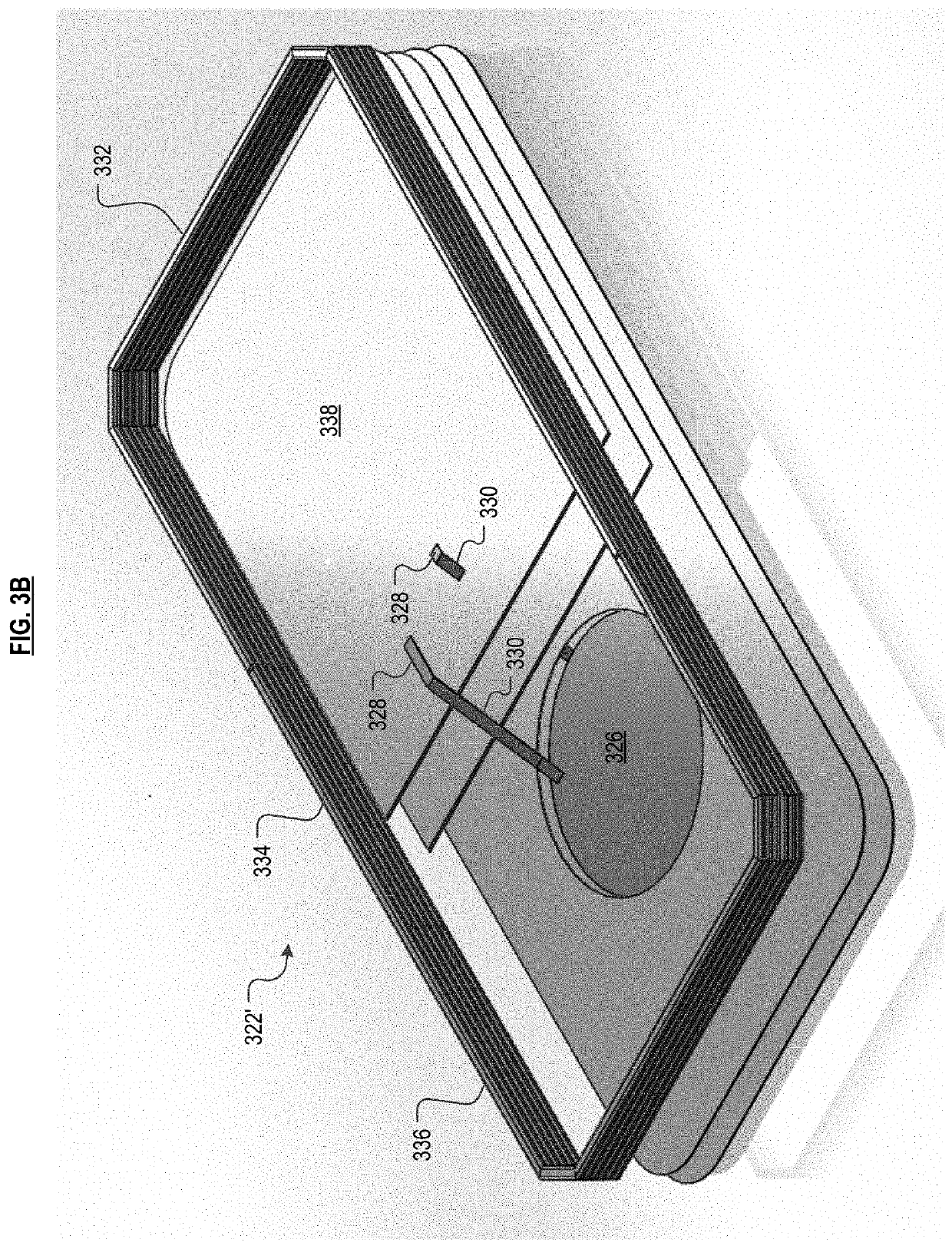
[0025]Definitions. The following terms are defined for use in this description and the appended claims:[0026]“Tow” means a bundle of fibers (i.e., fiber bundle), and those terms are used interchangeably herein unless otherwise specified. Tows are typically available with fibers numbering in the thousands: a 1K tow, 4K tow, 8K tow, etc.[0027]“Prepreg” means fibers that are impregnated with resin.[0028]“Towpreg” means a fiber bundle (i.e., a tow) that is impregnated with resin.[0029]“Preform” means a bundle of plural, unidirectionally aligned, same-length, resin-wetted fibers. The bundle is often (but not necessarily) sourced from a long length of towpreg. That is, the bundle is a segment of towpreg that has been cut to a desired size and, in many cases, is shaped (e.g., bent, twisted, etc.) to a specific form, as appropriate for the specific part being molded. The cross section of the preform, and the fiber bundle from which it is sourced typically has an aspect ratio (width-to-thick...


PUM

PropertyMeasurementUnit
aspect ratioaaaaaaaaaa
pressureaaaaaaaaaa

Abstract

A fiber-composite part having one or more electronic components that are located in arbitrary regions of the internal volume of the part are fabricated using a preform charge. The preform charge has a structure that corresponds to that of the mold cavity in which the part is being formed. By incorporating the electronic components in the preform charge, such components are then precisely located, spatially oriented, and constrained, and such location and orientation is maintained during molding to produce a part with the electronic components in the desired locations and orientations within its internal volume.

Description

FIELD OF THE INVENTION[0001]The present invention pertains to additive molding of fiber-composite materials.BACKGROUND OF THE INVENTION[0002]For many applications, it would be desirable to have a fiber-composite part that incorporates electronic components. For such applications, incorporated electronics will typically need to be at a precise location so as to properly interface with other electronic components on other parts.[0003]Currently, technologies for fabricating molded parts are limited in terms of their ability to “embed” electronics; that is, there is an inability to locate an electronic component at an arbitrary location within the volume of a part. An exception to this is multi-step molding techniques, such as “over-molding,” wherein a portion of a part is formed with an electronic component at its surface, and then further molding steps are performed in which additional resin is added, covering the component.[0004]In a single-step compression-molding process, however, ...

Claims


Application Information

Patent Timeline
Patent Type & Authority Applications(United States)
IPC IPC(8): B29C70/70H05K1/18H05K3/30H05K1/03
CPCB29C70/70H05K1/185B29K2309/08H05K1/0366H05K3/30B29C70/865H05K2201/0275B29K2307/04B29K2101/12B29K2105/0881B29L2031/34
Inventor ESCOWITZ, ETHANREESE, RILEYPERKINS, J. SCOTTDAVIDSON, ERICK
Owner ARRIS COMPOSITES INC
Learn More