Multi-Objective, Robust Constraints Enforced Global Topology Optimizer for Optical Devices

a global topology optimization and multi-objective technology, applied in the field of systems and methods for optimizing the fabrication of optical devices, can solve the problems of all lacking the ability to strictly avoid the existence of tiny features

Pending Publication Date: 2021-11-18
THE BOARD OF TRUSTEES OF THE LELAND STANFORD JUNIOR UNIV
View PDF6 Cites 5 Cited by
  • Summary
  • Abstract
  • Description
  • Claims
  • Application Information

AI Technical Summary

Benefits of technology

[0010]In still various other embodiments, the method further includes determining an efficiency-constrained variable gradient of the constrained device based on the permittivity-constrained variable gradient.
[0011]In still various other embodiments, the efficiency-constrained variable gradient is further based on an efficiency-permittivity gradient.
[0012]In still various other embodiments, the efficiency-constrained variable gradient is calculated using the following equation:
[0013]In still various other embodiments, an efficiency-latent variable gradient is calculated at least partially using a latent variable gradient of the latent unconstrained variables in relation to constrained device calculated using the following equations:
[0014]In still various other embodiments, the efficiency grating in relation to the unconstrained latent variables is calculated at least partially using the following equation:
[0015]In still various other embodiments, the efficiency-permittivity gradient is calculated using an adjoint variable method.

Problems solved by technology

A challenge in the inverse design of metasurfaces is to not only optimize device performance but also guarantee device fabricability, for example, enforcing control on the minimum feature size of the pattern so that the fabrication requirement will not go beyond the ability of lithography and etching.
Although existing strategies to restrict the minimum feature size such as applying filters and employing analytical penalty functions are able to tackle the problem to some extent, they all lack the ability to strictly avoid the existence of tiny features.

Method used


Image

  • Multi-Objective, Robust Constraints Enforced Global Topology Optimizer for Optical Devices
  • Multi-Objective, Robust Constraints Enforced Global Topology Optimizer for Optical Devices
  • Multi-Objective, Robust Constraints Enforced Global Topology Optimizer for Optical Devices

Examples


example optimization

Method

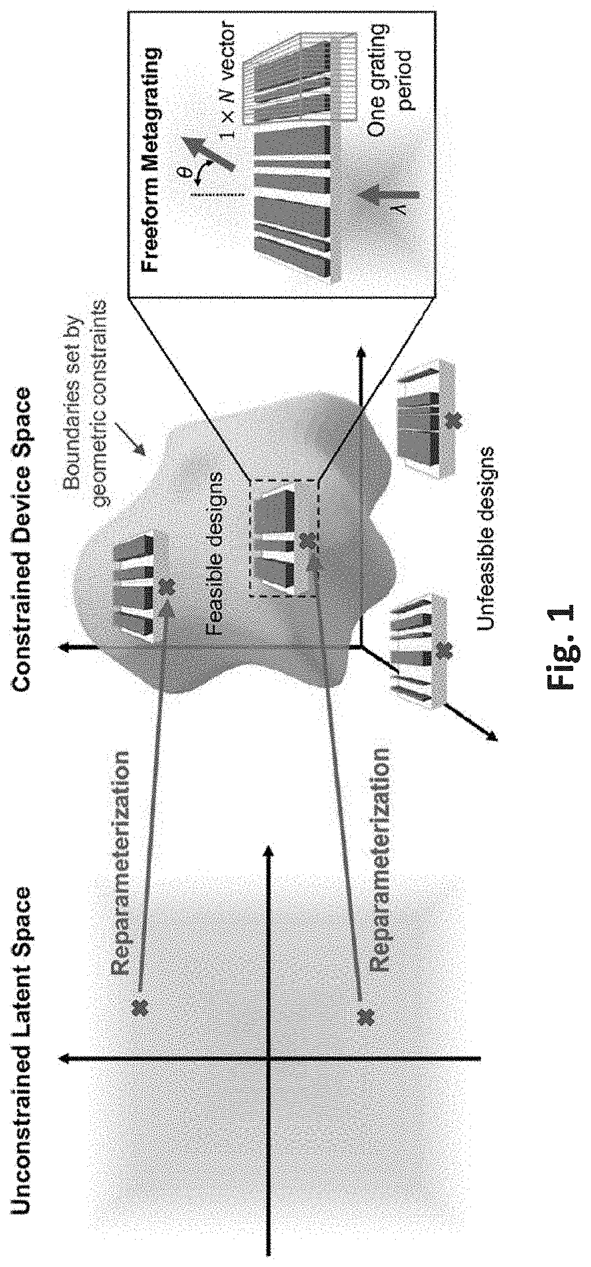
[0170]FIG. 34 illustrates an example optimization method 3400 in accordance with embodiments of the invention. The optimization method 3400 includes receiving (3402) a set of unconstrained latent variables. A generator may be used to generate the set of unconstrained latent variables. The generator may be updated at least partially based on a permittivity-constrained width gradient. The set of unconstrained latent variables may be initially randomly generated.

[0171]The optimization method 3400 may further include mapping (3404) the set of unconstrained latent variables to a constrained space to generate a constrained device. The mapping may include reparameterization of the unconstrained latent variables. the reparameterization of the unconstrained latent variables may include solving for a set of constrained width space {wi} through the following equations:

vi=Sigmoid⁡(ui),vM=1;ki=vi⁢1-∑j=1i-1⁢kj2,k1=v1;andwi=ki∑j=1M⁢kj⁢(L-Mwmin)+wmin,

where the set of unconstrained latent vari...


PUM


Abstract

A method for optimization of photonic devices is disclosed. The method includes receiving a set of unconstrained latent variables; mapping the set of unconstrained latent variables to a constrained space to generate a constrained device; calculating the permittivity across each element of the constrained device; determining a permittivity-constrained width gradient based at least partially on the permittivity across each element; and optimizing the set of unconstrained latent variables by at least partially using the permittivity-constrained width gradient.

Description

CROSS-REFERENCE TO RELATED APPLICATIONS[0001]This application claims the benefit of and priority under 35 U.S.C. § 119(e) to U.S. Provisional Patent Application Ser. No. 63 / 023,766 entitled “Multi-objective, Robust Constraints Enforced Global Topology Optimizer for Photonic Devices,” filed May 12, 2020, which is incorporated herein by reference in its entirety for all purposes.STATEMENT OF FEDERAL SUPPORT[0002]This invention was made with government support under Contract No. DE-AR0001212 awarded by the Department of Energy. The Government has certain rights in the invention.FIELD OF THE INVENTION[0003]This disclosure relates to systems and methods for optimizing fabrication of optical devices.BACKGROUND[0004]Optical devices such as metasurfaces may benefit from optimization. Metasurfaces are wavefront shaping devices with subwavelength-scale structures which have been demonstrated for a broad range of applications in sensing, imaging, and information processing. Inverse design usin...

Claims


Application Information

Patent Timeline
Patent Type & Authority Applications(United States)
IPC IPC(8): G02B27/00G01M11/02G06N3/04
CPCG02B27/0012G06N3/04G01M11/0242G01M11/0228G02B1/002G06N3/088G06N3/084G06N3/047G06N3/045
Inventor FAN, JONATHANJIANG, JIAQICHEN, MINGKUN
Owner THE BOARD OF TRUSTEES OF THE LELAND STANFORD JUNIOR UNIV
Why Eureka
Try Eureka