

Endoscope and method of use
a technology of endoscope and working channel, which is applied in the field of endoscope and its use, can solve the problem of limited working channel size of hysteroscop
- Summary
- Abstract
- Description
- Claims
- Application Information
AI Technical Summary
Benefits of technology
Problems solved by technology
Method used
Image

Examples
Embodiment Construction
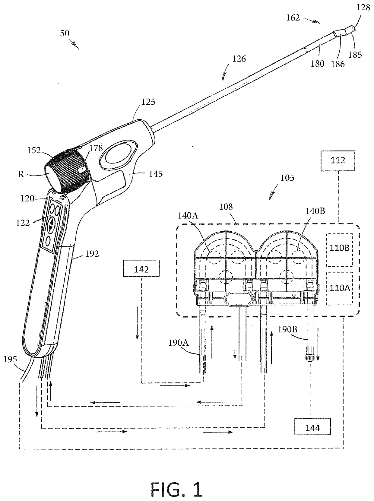
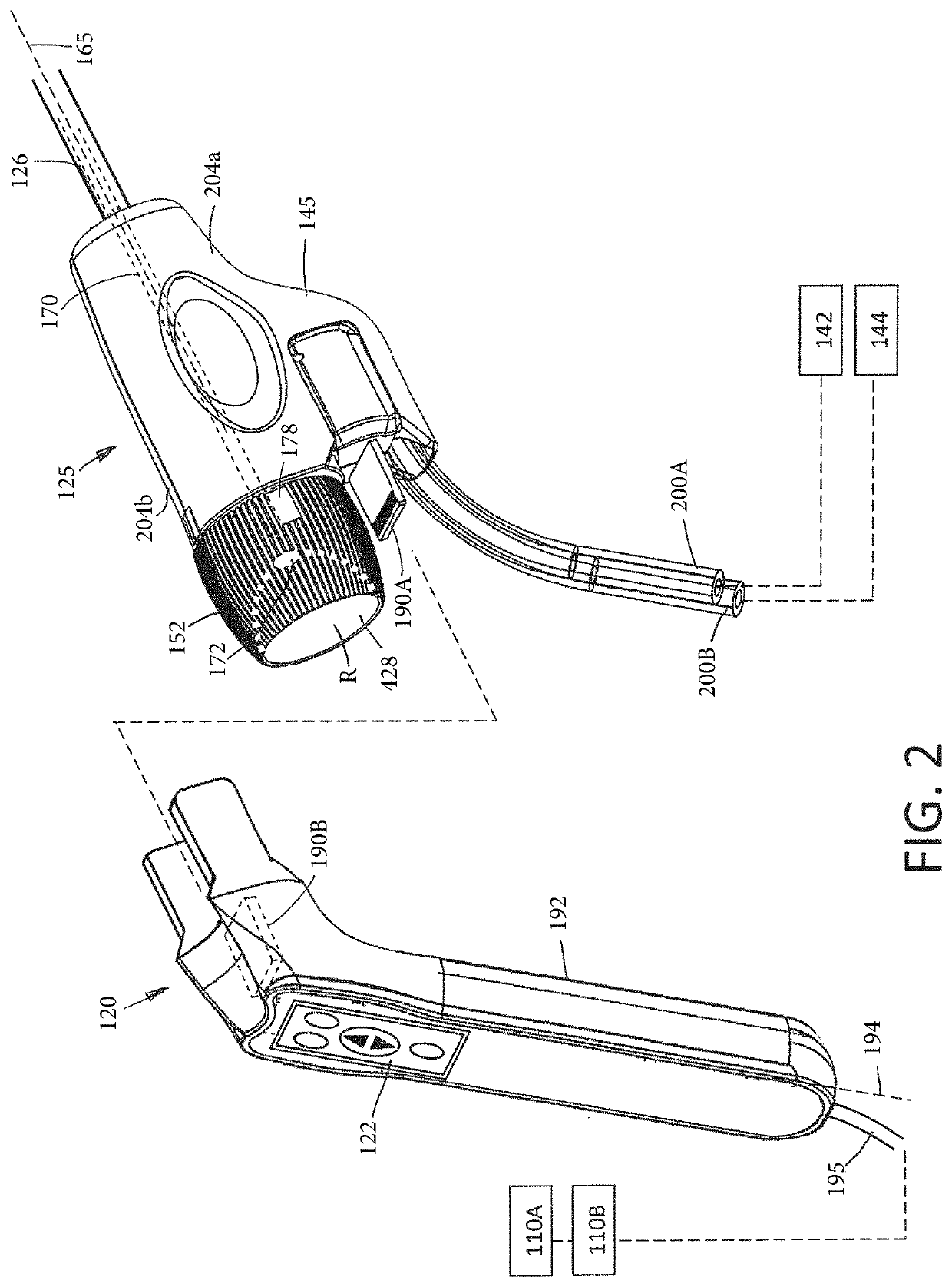
[0042]FIG. 1 illustrates a hysteroscopic treatment system 50 corresponding to the invention which comprises multiple components including an endoscopic viewing system 100 and a fluid management system 105 housed in a base unit or console 108. The base unit 108 also carries a controller 110A and power source for operating the system 50 and can include an image processor 110B for processing signals from an image sensor carried by the endoscopic viewing system. A display 112 can be coupled to the base unit 108 for viewing images provided by the endoscopic viewing system 100.
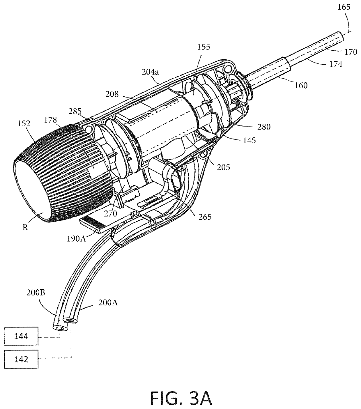
[0043]More in particular, the endoscopic viewing system 100 of FIGS. 1 and 2 includes a re-usable handle component 120 with a finger-actuated control pad 122 and a disposable single-use endoscope component 125 with an elongated endoscope shaft 126 that carries a distal electronic imaging sensor 128 (see FIGS. 1 and 7A). The fluid management system 105 includes a first peristaltic inflow pump 140A and second peristal...
PUM
 Abstract
Description
Claims
Application Information