Cooling box for a shaft furnace

Active Publication Date: 2021-12-02
PAUL WURTH SA +1
View PDF0 Cites 0 Cited by
  • Summary
  • Abstract
  • Description
  • Claims
  • Application Information

AI Technical Summary

Benefits of technology

The patent describes a new design of a cooling box that is more cost-effective and time-efficient to manufacture. The cooling circuit is built using form-fit connections between added partition plates and the body, without the need for welding. The partition plate is secured inside the inner chamber by a cover plate that applies a pressure load on it, and a gasket improves the sealing connection between the cover plate and the rear wall of the body. The cover plate is fixed to the rear wall with screws, without the need for welding or special skills. Overall, this design provides a more robust cooling box that is efficient to manufacture and assemble.

Problems solved by technology

As the inner lining of the furnace wall erodes, cooling boxes become exposed to the harsh operating conditions inside the furnace.
Erosion and damage of cooling boxes occurs and maintenance operations have to be performed to replace damaged cooling boxes.
Due to the large number of cooling boxes mounted on a furnace wall and their replacement, the manufacturing cost of a cooling box is a critical constraint in the development of a new cooling box.
This method allows complicated shapes of cooling circuit to be built inside the cooling box, but its main drawback is that the sand casting step requires a long manufacturing process including preparation of the mould, and eventually further operations for drilling evacuation holes for the sand, and then closing the holes that will have no other further purposes.
However, this method also involves a complex and expensive step of explosion welding.

Method used


Image

  • Cooling box for a shaft furnace
  • Cooling box for a shaft furnace
  • Cooling box for a shaft furnace

Examples


second embodiment

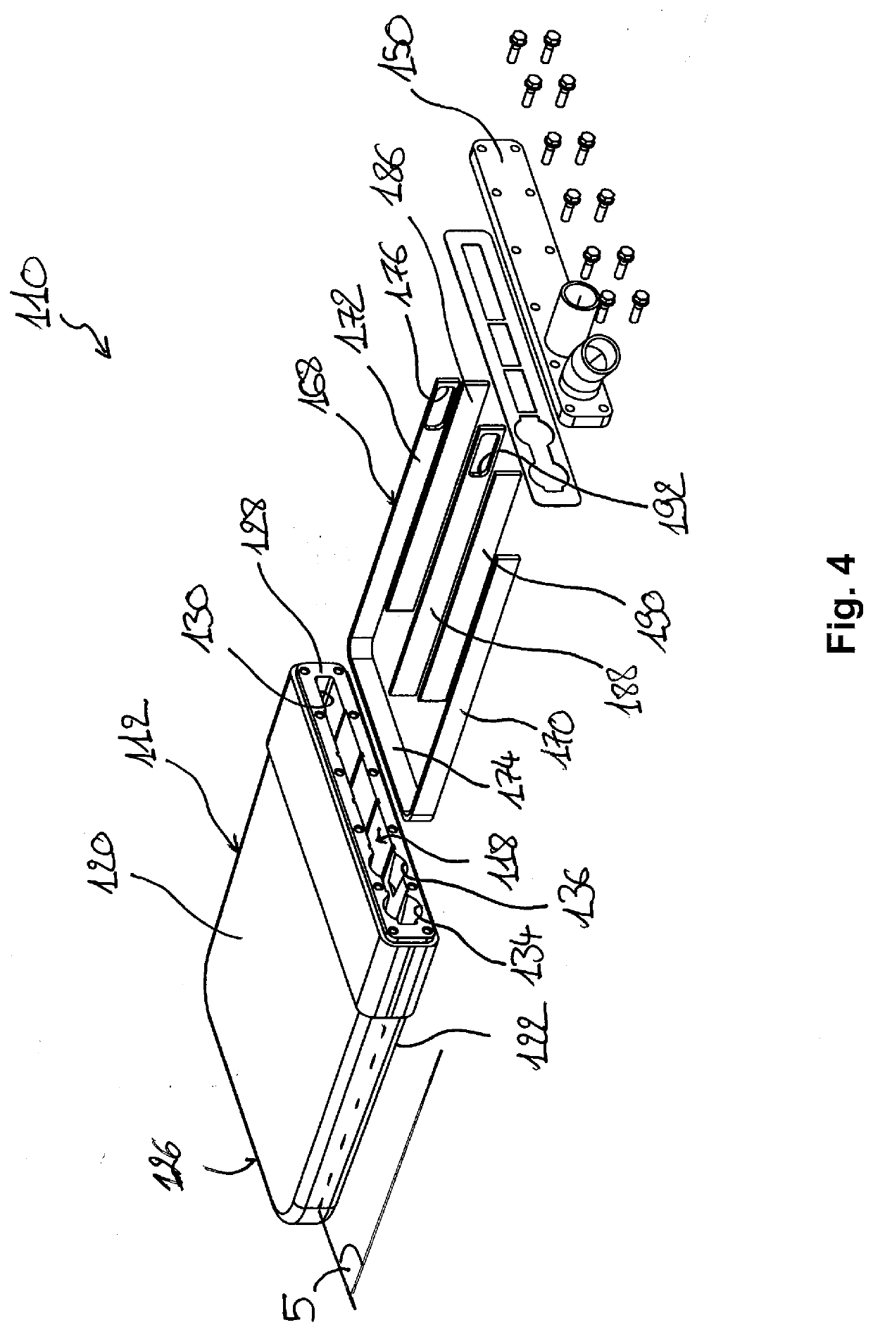
[0063]Manufacturing of the cooling box 110 according to this second embodiment comprises the same steps as for the previous embodiment, with slightly different operations as described below.

[0064]A first partition plate 170 and a fifth partition plate 172 are formed by the legs of a U-shaped element 168 dimensioned to extend inwardly parallel to the peripheral walls of the body 112 to create a path of constant width adjacent to the peripheral walls. The U-shaped partition plate 168 comprises a connecting web 174 perpendicular to its legs and joining the ends of the first and fifth partition plates 170, 172. The first partition plate 170 is disposed between the inlet 134 and the outlet 136. A free end of the fifth partition plate 172 comprises a first aperture 176 near the opening 130 in order to allow coolant fluid to pass through the fifth partition plate 172. The connecting web 174 of the U-shaped element 168 forms a channel near a front wall 126 of the body 112, this channel bein...

first embodiment

[0069]The second, third and fourth partition plates 190, 188, 186 are engaged in a form-fit connection inside the inner chamber 118 in straight slots 146 formed in the distal faces 182 of the top and bottom walls 120, 122, extending from the opening 130 of the rear wall 128. As an alternative to the first embodiment, the second, third and fourth partition plates 190, 188, 186 are here not provided with corresponding tongues but engage with their edges directly into the slots 146. Insertion of the second, third and fourth partition plates 190, 188, 186 in the slots is similar to the previous embodiment provided that the second, third and fourth partition plates 190, 188, 186 are inserted after the U-shaped element plate168.

[0070]Closest to the fifth partition plate 172, the fourth partition plate 186 has a length smaller than the length of the second leg of the U-shaped element 168 leaving a passage for the flow of cooling fluid. Then, the third partition plate 188 is dimensioned to ...


PUM


Abstract

A cooling box for a metallurgical furnace including an elongated hollow body extending from a front end, to an opposite rear end, the rear end being, in use, connected to a wall of the furnace; the body includes an inner chamber having a cooling circuit configured to receive a flow of coolant fluid therein between at least one inlet and at least one outlet; the cooling box further including at least one partition plate fitted in the inner chamber through a form-fit connection to form the cooling circuit.

Description

TECHNICAL FIELD[0001]The present disclosure relates to a cooler for cooling internal plates of a shaft furnace. The disclosure particularly relates to a cooling box and a method for manufacturing a cooling box for cooling the internal wall of a shaft furnace.BACKGROUND[0002]It is well known to provide blast furnace walls with coolers in order to dissipate the heat in the furnace wall and thereby increase the service life of the furnace. Coolers are generally mounted in a lining of the furnace wall requiring an important number of adjacent coolers. The type of cooler that interests us here is the so called cooling box.[0003]A cooling box is typically made out of copper, steel or an alloy. It has a shape which is roughly that of a flattened parallelepiped, and it is provided with one or more cooling circuits; i.e. a path through which coolant fluid, like for example water, circulates.[0004]Cooling boxes are usually welded to the blast furnace shell to ensure gas tight sealing and serv...

Claims


Application Information

Patent Timeline
IPC IPC(8): C21B7/10F27D1/12
CPCC21B7/106F27D2009/0021F27D1/12F27B1/24F27D2009/0043
Inventor OLIVIERI, STEFANOMICHELETTI, LORENZOCRAVINO, FABIO
Owner PAUL WURTH SA
Why Eureka
Try Eureka