Floating connector

a technology of floating connectors and connectors, applied in the direction of coupling contact members, coupling device connections, coupling/insulating coupling contact members, etc., can solve the problems of long contact, inability to resist deformation, and damage to contact b>92/b>, etc., to achieve the effect of reducing the impedance of conta

Active Publication Date: 2021-12-02
JAPAN AVIATION ELECTRONICS IND LTD
View PDF0 Cites 0 Cited by
  • Summary
  • Abstract
  • Description
  • Claims
  • Application Information

AI Technical Summary

Benefits of technology

[0011]The floating connector of the present invention is provided with the plurality of the contacts and the at least one stub member corresponding to the at least one of the contacts in one-to-one correspondence. The stub member has the stub contact point. The stub contact point is always pressed against the contact corresponding to the stub member even when the movable housing is moved within the predetermined range. With this structure, an impedance of the contact can be reduced without providing a wide adjustment portion to the contact.

Problems solved by technology

However, a long contact is undesirable for signal transmission, especially high-speed signal transmission, because it has a high impedance.
However, the wide adjustment portion 98 is hard to be resiliently deformed.
As a result, the floating connector 90 of Patent Document 1 has a problem that the contact 92 may be damaged due to stress concentration.

Method used


Image

  • Floating connector
  • Floating connector
  • Floating connector

Examples


first embodiment

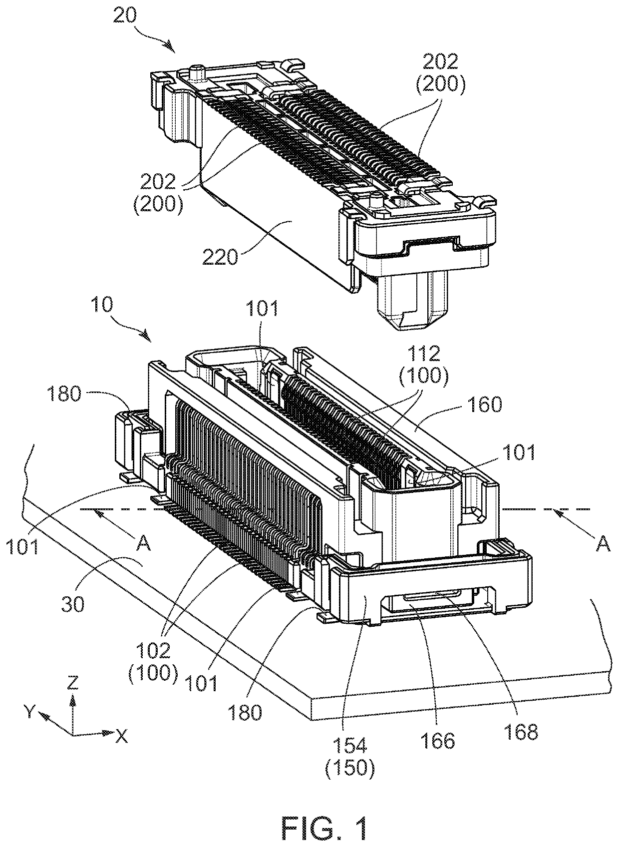
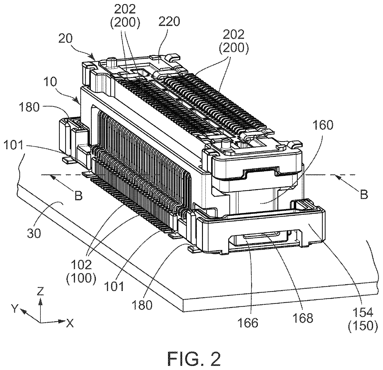
[0043]Referring to FIGS. 1 and 2, a floating connector 10 according to a first embodiment of the present invention is mounted on a substrate 30 when used. The floating connector 10 is mateable with and removable from a mating connector 20 along a mating direction perpendicular to the substrate 30. In the present embodiment, the mating direction is an up-down direction or a Z-direction. A positive Z-direction is directed upward while a negative Z-direction is directed downward.

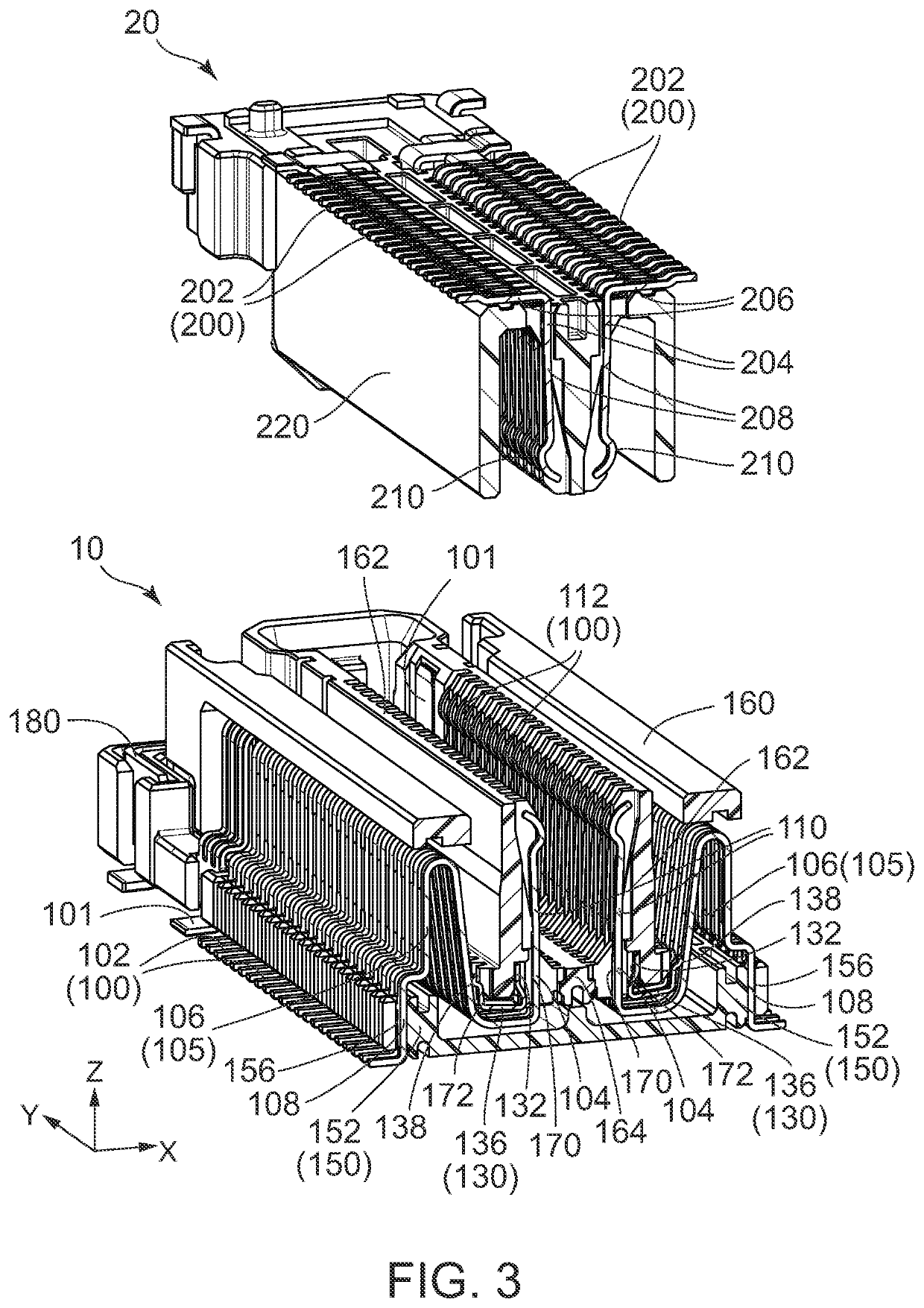
[0044]As shown in FIGS. 3 and 4, the mating connector 20 is provided with a plurality of mating contacts 200 and a mating housing 220. The mating contacts 200 are made of metal, and the mating housing 220 is made of insulating resin. The mating housing 220 has a shape long in a pitch direction perpendicular to the up-down direction. The mating contacts 200 are arranged in two rows along the pitch direction and held by the mating housing 220. In the present embodiment, the pitch direction is a Y-direction. Howev...

second embodiment

[0069]Referring to FIGS. 12 to 14, a floating connector 10A according to a second embodiment of the present invention has stub members 130A each of which has a shape different from that of the stub member 130 of the floating connector 10 according to the first embodiment. In other words, the floating connector 10A of the present embodiment is formed similarly to the floating connector 10 of the first embodiment except for the stub members 130A.

[0070]As shown in FIGS. 15 to 17, each of the stub members 130A in the floating connector 10A of the present embodiment has a held portion (a second held portion) 132, a supporting portion 136 and a stub contact point 138. The held portion 132 has a plate shape which is perpendicular to the lateral direction and long in the up-down direction. The held portion 132 further has a narrow portion 140 near the middle portion thereof in the up-down direction. Furthermore, on a surface of the held portion 132, a protruding portion 134 is provided. In ...

third embodiment

[0073]Referring to FIG. 18, a floating connector 10B according to a third embodiment of the present invention has stub members 130B each of which is different from the stub member 130A of the floating connector 10A of the second embodiment in position and shape. In connection with this, the floating connector 10B of the present embodiment is provided with contacts 100B and a movable housing 160B which are different from the contacts 100 and the movable housing 160 of the floating connector 10A of the second embodiment, respectively. In other words, the floating connector 10B of the present embodiment is formed similarly to the floating connector 10A of the second embodiment except for the movable housing 160, the stub members 130B and the contacts 100B.

[0074]As shown in FIGS. 19 to 21, each of the stub members 130B in the floating connector 10B of the present embodiment has a held portion (a second held portion) 132, a supporting portion 136 and a stub contact point 138. The held po...


PUM


Abstract

A floating connector is provided with a plurality of contacts, at least one stub member and a movable housing. The movable housing has a first holding portion and a second holding portion. The first holding portion holds first held portions of the contacts, and the second holding portion holds a second held portion of the stub member. The at least one stub member corresponds to at least one of the contacts in one-to-one correspondence. A stub contact point is always pressed against a coupling portion of the contact corresponding to the stub member even when the movable housing is moved within a predetermined range.

Description

CROSS REFERENCE TO RELATED APPLICATIONS[0001]This application is based on and claims priority under 35 U.S.C. § 119 to Japanese Patent Application No. JP2020-093259 filed May 28, 2020, the contents of which are incorporated herein in their entirety by reference.BACKGROUND OF THE INVENTION[0002]This invention relates to a floating connector.[0003]An example of a floating connector is disclosed in JP2019-114565A (Patent Document 1). As shown in FIG. 29, a floating connector 90 of Patent Document 1 is provided with a plurality of contacts 92, a first insulator (or a fixed housing) 94 and a second insulator (or a movable housing) 96. Each of the contacts 92 is held by the first insulator 94 and held by the second insulator 96. The contact 92 is resiliently deformable in part. The second insulator 96 is movable with respect to the first insulator 94 by using resilient deformation of the contacts 92. Accordingly, when the floating connector 90 and a mating connector (not shown) are mated ...

Claims


Application Information

Patent Timeline
Patent Type & Authority Applications(United States)
IPC IPC(8): H01R12/91H01R12/71
CPCH01R12/91H01R12/71H01R13/02H01R13/502H01R12/716H01R12/57H01R12/73H01R13/41H01R13/6474H01R13/6315H01R43/16H01R13/11
Inventor OBATA, YUSUKETOKUNAGA, TAKASHITAKIKAWA, KAZUKIHORI, KIICHI
Owner JAPAN AVIATION ELECTRONICS IND LTD
Why Eureka
Try Eureka