Electrode and sensor

a technology applied in the field of electrodes and sensors, can solve problems such as characteristics deterioration, and achieve the effects of reducing contact impedance of living bodies, accurate potential measurements, and deterioration of mountability

Pending Publication Date: 2021-01-14
SONY CORP
View PDF0 Cites 0 Cited by
  • Summary
  • Abstract
  • Description
  • Claims
  • Application Information

AI Technical Summary

Benefits of technology

[0053]As described above, a wet electrode is typically used for a biopotential measurement. The wet electrode makes it possible to reduce a contact impedance of a living body by interposing an electrolyte gel between a metal electrode and skin. However, a measurement with use of the wet electrode using the electrolyte gel raises an issue with deterioration in characteristics over time due to evaporation of the moisture contained in the electrolyte gel, or contamination caused by the electrolyte gel.
[0054]Therefore, a dry electrode has been proposed that avoids interposition of the electrolyte gel. A representative example of the dry electrode includes metal or a metal compound. An issue with the dry electrode includes difficulty in getting good contact with the skin of a body portion having body hair, such as the head, and difficulty with accurate potential measurement. As a method of solving such an issue, a typical method is adopted that uses a comb-shaped electrode to contact with the skin through gaps in the hair; however, pain or difficulty in mounting still remains as an issue. Further, in a portion with less body hair, it is pointed out that degradation in the signal quality is caused because a state of good contact with the skin is unobtainable due to hardness of metal, or deterioration in the mountability is caused due to incrustation or the like.
[0055]In recent years, as a method of forming a biopotential electrode that is superior in terms of mountability, a method has been proposed that forms an electrode resin by mixing conductive particles in an elastomer. Such a method typically uses carbon or the like as the conductive particle; however, carbon-mixed resin polarizes due to contact with a living body, which raises an issue of difficulty with accurate biopotential measurement. As a method of preventing such an issue, a method has been proposed that coats a contact portion to be brought into contact with the skin with silver chloride (AgCl); however, a portion of the silver chloride (AgCl) is likely to drop off, and thus improvement in the mechanical reliability is desired.
[0056]In contrast, in the present embodiment, the conductive material and the non-polarizable material having the non-polarizable property and ionic bonding are dispersed in the substrate that forms the electrode 1, and the regions different from each other in the concentration ratio between the conductive material and the non-polarizable material are formed in a contact portion to be brought into contact with an object and a non-contact portion of the electrode 1. Specifically, the first region 11 with higher concentration of the non-polarizable material than that of the conductive material is formed in the contact portion to be brought into contact with the object, and the second region 12 with higher concentration of the conductive material than that of the non-polarizable material is formed in the non-contact portion. In a case where the object is a living body, this makes it possible to prevent polarization of the contact portion brought into contact with the living body. Further, the non-polarizable material is dispersed in the substrate along with the conductive material, and the first region 11 having the non-polarizable material in high concentration and the second region 12 are formed in an integrated manner, which makes it possible to prevent drop-off of a portion of the non-polarizable material, or the like.
[0057]As described above, in the electrode 1 of the present embodiment, the conductive material and non-polarizable material are dispersed in the substrate; the first region 11 and the second region 12 are formed that are different from each other in a concentration ratio; and the first region 11 with higher concentration of the non-polarizable material than that of the conductive material is used as the contact portion to be brought into contact with a living body. This ensures to reduce polarization of the contact portion of the electrode 1 brought into contact with the living body, which allows for accurate biopotential measurement. Further, the first region 11 having the non-polarizable material in high concentration is formed in an integrated manner as the electrode 1, which prevents drop-off of a portion of the non-polarizable material, or the like. This makes it possible to provide an electrode that allows for the accurate biopotential measurement and exhibits the improved electrical and mechanical reliability.
[0058]Further, in the present embodiment, it is possible to distribute the non-polarizable material in high concentration at a desired local position through, for example, sedimentation in a fluidized state, centrifugal separation, or the like. This makes it possible to manufacture an electrode that exhibits the improved electrical and mechanical reliability at low cost and with ease.

Problems solved by technology

The measurement with use of the wet electrode involves applying an electrolyte gel between the electrode and skin, which raises an issue with deterioration in characteristics over time due to evaporation of the moisture contained in the electrolyte gel, or contamination caused by the electrolyte gel.

Method used


Image

  • Electrode and sensor
  • Electrode and sensor
  • Electrode and sensor

Examples


embodiment

1. EMBODIMENT

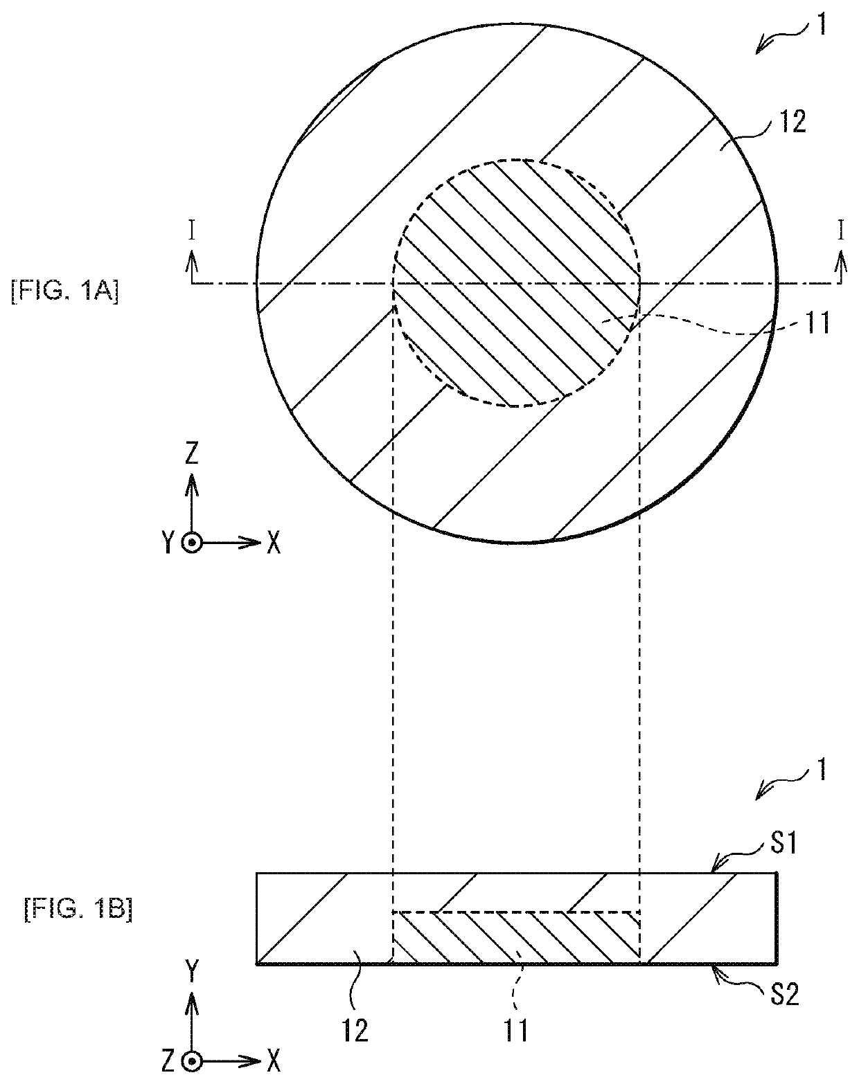
[0033]Part (A) of FIG. 1 schematically illustrates an example of a planar configuration of an electrode (an electrode 1) according to an embodiment of the present disclosure, and Part (B) of FIG. 1 schematically illustrates an example of a cross-sectional configuration of the electrode 1 taken along a line I-I illustrated in Part (A) of FIG. 1. The electrode 1 is used as an electrode of a biological sensor that is brought into contact with a living body to measure the potential, for example. The electrode 1 of the present embodiment has a configuration in which, in a substrate forming the electrode 1, a conductive material (a first conductive material) and a conductive material having non-polarizable property and ionic bonding (a second conductive material, hereinafter referred to as a non-polarizable material) are included, and a first region 11 and a second region 12 are formed that are different from each other in the concentration ratio between the conductive materi...

application examples

2. APPLICATION EXAMPLES

[0059]Next, description is provided of application examples of an electronic apparatus that includes the electrode 1 (or any of the electrodes 1A to 1C) described in the above embodiment. However, the configuration of the electronic apparatus described below is merely an example, and it is possible to change the configuration as appropriate. The above-described electrode 1 is applicable to various sensors, various electronic apparatuses, or a portion of furnishings that detect or measure, for example, perspiration, body temperature, a perspiration ingredient, skin gas, blood sugar, and the like. For example, the above-described electrode 1 is applicable, as a so-called wearable device, to a portion of furnishings such as a watch (a wristwatch), a bag, clothes, a hat or a cap, glasses, and shoes. Types of the applicable electronic apparatuses and the like are not particularly limited.

application example 1

[0060]FIG. 6 illustrates a schematic configuration of a biopotential sensor. The electrode 1 of the present embodiment is usable as a measuring section (a sensor 110) that allows for measuring a biopotential or a bioimpedance by performing modification or geometric processing on an electrode surface on an as-needed basis, and by coupling the electrode 1 to a controller 120, a wiring line 130, and a circuit 140.


PUM

PropertyMeasurementUnit
particle sizeaaaaaaaaaa
non-polarizable propertyaaaaaaaaaa

Abstract

An electrode according to an embodiment of the present disclosure includes: a first conductive material; a second conductive material having non-polarizable property and ionic bonding; and a substrate that includes the first conductive material and the second conductive material, and has a first region and a second region that are different from each other in a concentration ratio between the first conductive material and the second conductive material.

Description

TECHNICAL FIELD[0001]The present disclosure relates to an electrode that is used in, for example, a biopotential measurement, and a sensor that includes such an electrode.BACKGROUND ART[0002]Typically, a biopotential measurement uses a wet electrode. The measurement with use of the wet electrode involves applying an electrolyte gel between the electrode and skin, which raises an issue with deterioration in characteristics over time due to evaporation of the moisture contained in the electrolyte gel, or contamination caused by the electrolyte gel.[0003]Therefore, a dry electrode has been proposed that avoids the use of the electrolyte gel. In recent years, to form a biopotential electrode with superior mountability, a method has been proposed that forms an electrode resin by mixing conductive particles such as, for example, carbon in an elastomer (for example, see NPTL 1). Further, an electrode has been proposed that includes carbon-mixed resin and has a silver-chloride (AgCl)-coated...

Claims


Application Information

Patent Timeline
Patent Type & Authority Applications(United States)
IPC IPC(8): A61B5/053
CPCA61B5/053A61B5/14517A61B5/14532A61B5/268A61B5/265A61B2562/12
Inventor KATSUHARA, MAO
Owner SONY CORP
Why Eureka
Try Eureka