Inductance and current flow estimations

a current flow and inductance technology, applied in the field of inductance and current flow estimation, can solve the problems of errors associated with estimating the actual output current, deficiencies in conventional power supply monitoring and control techniques, etc., and achieve the effect of less steep slope and difficulty in obtaining precise time and magnitude information

Active Publication Date: 2021-12-09
INFINEON TECH AUSTRIA AG
View PDF1 Cites 2 Cited by
  • Summary
  • Abstract
  • Description
  • Claims
  • Application Information

AI Technical Summary

Benefits of technology

[0095]As previously discussed, embodiments herein include the observation that the current sense signal 147 may accurately depict the amount of output current 122 through the inductor 225 for one or more first portions (such as window 521, window 522, window 523, etc.) of the current sense signal 147; the current sense signal 147 may be inaccurate in depicting the amount of current 122 through the inductor 225 for one or more second portions (such as outside of window 521 between time TW11 and TW12, outside of window 522 between time TW13 and TW15, outside of window 523 between time TW15 and TW17, etc.) of the cu...

Problems solved by technology

This disclosure includes the observation that conventional power supply monitoring and control techniques suffe...

Method used


Image

  • Inductance and current flow estimations
  • Inductance and current flow estimations
  • Inductance and current flow estimations

Examples


Embodiment Construction

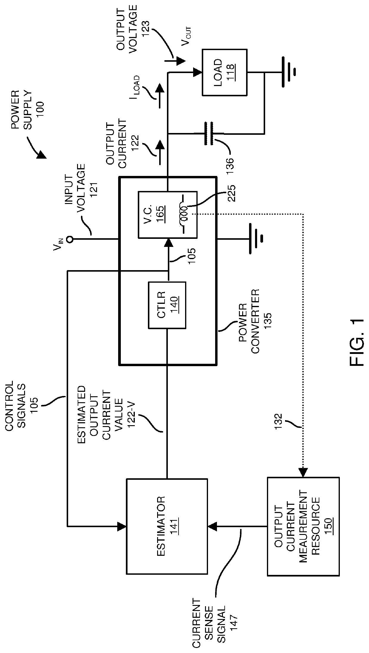
[0045]Embodiments herein include an apparatus comprising a power converter and a current estimator. The power converter produces an output voltage to power a load via current through an inductor. The estimator receives a current sense signal from a current monitor resource. The current sense signal represents a measured magnitude of the current supplied to the load through the inductor over time during one or more power delivery control cycles. Via the current sense signal, the estimator first determines an inductance (value) of the inductor. The estimator then uses the estimated inductance value to further determine a magnitude of the output current supplied through the inductor to the load.

[0046]Now, more specifically, FIG. 1 is an example general diagram of a power supply supporting inductance measurements and inductor current estimation according to embodiments herein.

[0047]In this example embodiment, the power supply 100 includes power converter 135, estimator 141, and output c...


PUM


Abstract

An apparatus includes a power converter and an estimator. The power converter produces an output voltage to power a load via current through an inductor. The estimator receives a current sense signal from a current monitor resource. The current sense signal represents/indicates a measured magnitude of the current supplied to the load through the inductor over time during one or more power delivery control cycles. Portions of the current sense signal may be an inaccurate representation of an amount of current through the inductor. Via the current sense signal, or portion thereof, the estimator determines (such as calculates) an inductance (value) of the inductor. The estimator then uses the calculated inductance value to estimate a magnitude of the output current supplied through the inductor to the load.

Description

BACKGROUND[0001]One type of conventional power converter is a buck converter. In general, to maintain an output voltage within a desired range, a controller in the buck converter compares the magnitude of a generated output voltage to a setpoint reference voltage. Based on a respective error voltage, the controller modifies a respective switching frequency and / or pulse width modulation associated with activating high side switch circuitry or low side switch circuitry in the buck converter.[0002]In certain instances, the controller controls operation of the buck converter based on an amount of output current supplied by a generated output voltage to a load.[0003]The output current can be measured in any suitable manner such as DCR current sensing across an inductor, current mirroring, sense resistance of switch circuitry, etc. In different conventional implementations, a corresponding analog-to-digital converter (ADC) monitors the output current tends to be slow and inaccurate.BRIEF ...

Claims


Application Information

Patent Timeline
IPC IPC(8): G01R19/25G01R19/165G01R19/257H02M7/00
CPCG01R19/2513H02M7/003G01R19/257G01R19/165G01R27/2611G01R19/252H02M1/00H02M3/158H02M1/0009H02M3/156
Inventor YOU, ZHIQINGNG, TIM
Owner INFINEON TECH AUSTRIA AG
Why Eureka
Try Eureka