
Heat exchange apparatus and method

Pending Publication Date: 2021-12-16
UT BATTELLE LLC
View PDF0 Cites 0 Cited by
  • Summary
  • Abstract
  • Description
  • Claims
  • Application Information

AI Technical Summary

Benefits of technology

The invention is a heat exchanger apparatus that includes a tube with a wall having an inner surface and an outer surface. The tube is designed to receive heat exchange fluid at one end and output the fluid as vapor at the other end. The apparatus includes a first layer of thermally conductive porous material on the inner surface and a second layer of thermally conductive porous material on the outer surface. The first layer can be made of copper, aluminum, or iron, and the second layer can be made of copper, aluminum, or iron. The apparatus can also include a ceramic coating on the first and second layers. The heat exchanger can be used in heating equipment or flow boilers. The technical effect of the invention is to improve heat transfer efficiency in heat exchangers by using a porous material with a cell diameter that increases from a first size proximate to the wall to a second size greater than the first size distal to the wall.

Problems solved by technology

If the fluid is not properly distributed, underutilization of the surface area will result.

Method used


Image

  • Heat exchange apparatus and method
  • Heat exchange apparatus and method
  • Heat exchange apparatus and method

Examples


Embodiment Construction

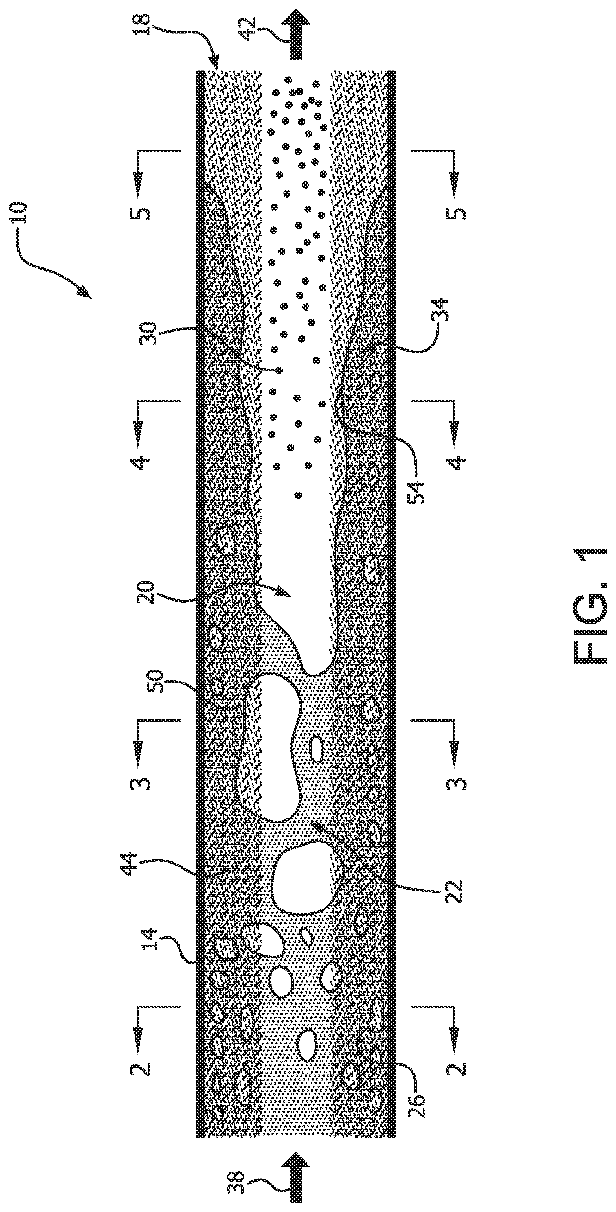
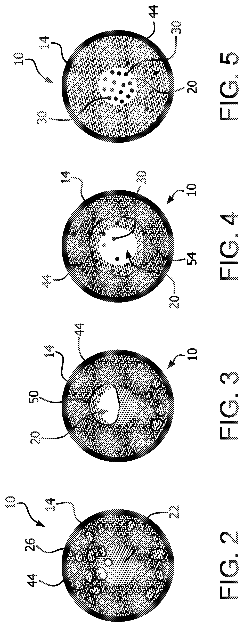
[0034]A heat exchanger includes a tube having a wall with an inner surface and an outer surface. The tube is configured to receive heat exchange fluid at one end, and output, when heated through the wall, vapor of the heat exchange fluid at the opposing end. A first layer of thermally conductive porous material is disposed on the inner surface of the tube.

[0035]The heat exchange fluid can be selected from many possible fluids. One such fluid is water, and the vapor of the heat exchange fluid can be steam. Other fluids can include hydrocarbons, refrigerants, oils and molten salts.

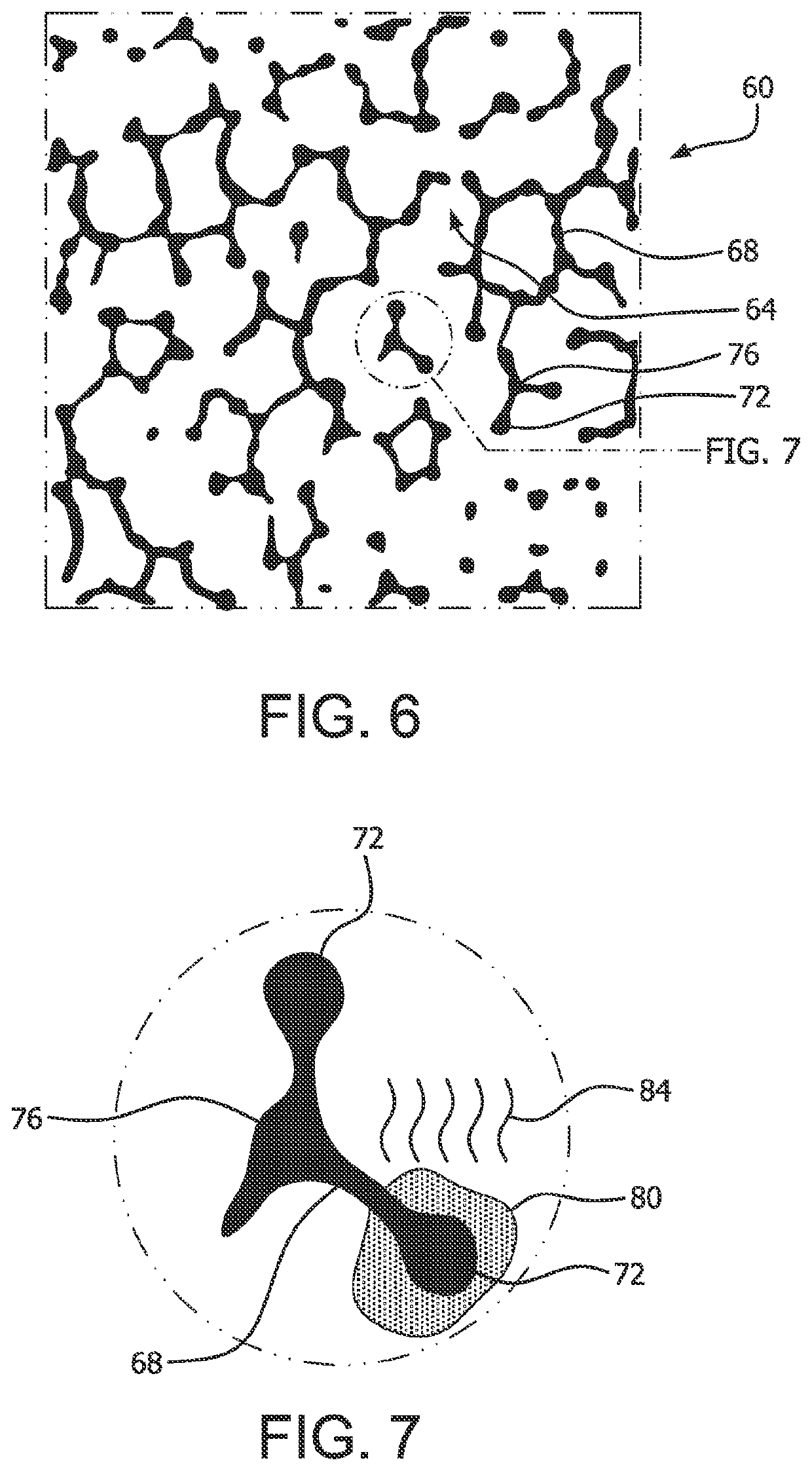
[0036]The thermally conductive porous material should have interconnected pores which permit fluid flow in at least two directions, and possibly three. Various open cell architectures are possible. Open cell foams in particular are desirable because should foams are readily formed and have both desirable flow characteristics and heat conduction. Different foam materials are possible. The foam material can in...


PUM


Abstract

A heat exchanger apparatus includes a tube having a wall with an inner surface and an outer surface. The tube is configured to receive heat exchange fluid at one end, and output, when heated through the wall, vapor of the heat exchange fluid at the opposing end. A first layer of thermally conductive porous material is disposed on the inner surface of the tube. Heating equipment, a heat exchanger, and a method of heating are also disclosed.

Description

CROSS-REFERENCE TO RELATED APPLICATIONS[0001]This application claims priority to U.S. 63 / 037,629 filed on Jun. 11, 2020, entitled “Natural Gas-Fired Boiler for Residential and Light Commercial Applications”, the entire disclosure of which incorporated herein by reference.STATEMENT REGARDING FEDERALLY SPONSORED RESEARCH AND DEVELOPMENT[0002]This invention was made with government support under Contract No. DE-AC05-00OR22725 awarded by the U.S. Department of Energy. The government has certain rights in this invention.FIELD OF THE INVENTION[0003]The present invention relates to heat exchange methods and devices, and more particularly to flow boiling heat exchange devices and methods.BACKGROUND OF THE INVENTION[0004]Flow boiling is a heat exchange process in which a liquid flows through a heat exchange tube or conduit, and absorbs heat flowing through the tube. As the liquid absorbs heat that is transferred through the wall of the tube and saturation conditions are reached, the process ...

Claims


Application Information

Patent Timeline
IPC IPC(8): F28F13/00F28F13/02F28F21/08
CPCF28F13/003F28F13/02F28F21/089F28F21/085F28F21/084F28F21/082F28F13/187F28D2021/0064F28D2021/0071F28F21/04F22B37/10B01D1/065B01B1/06B01B1/02F24H1/41
Inventor NAWAZ, KASHIF
Owner UT BATTELLE LLC
Learn More