
Smart sensing system

a sensing system and intelligent technology, applied in the field of sensing, can solve problems such as damage to the structure, failure of the structure, and formation of microscopic pores which may extend

Pending Publication Date: 2022-01-06
ZENSOR NV +1
View PDF4 Cites 0 Cited by
  • Summary
  • Abstract
  • Description
  • Claims
  • Application Information

AI Technical Summary

Benefits of technology

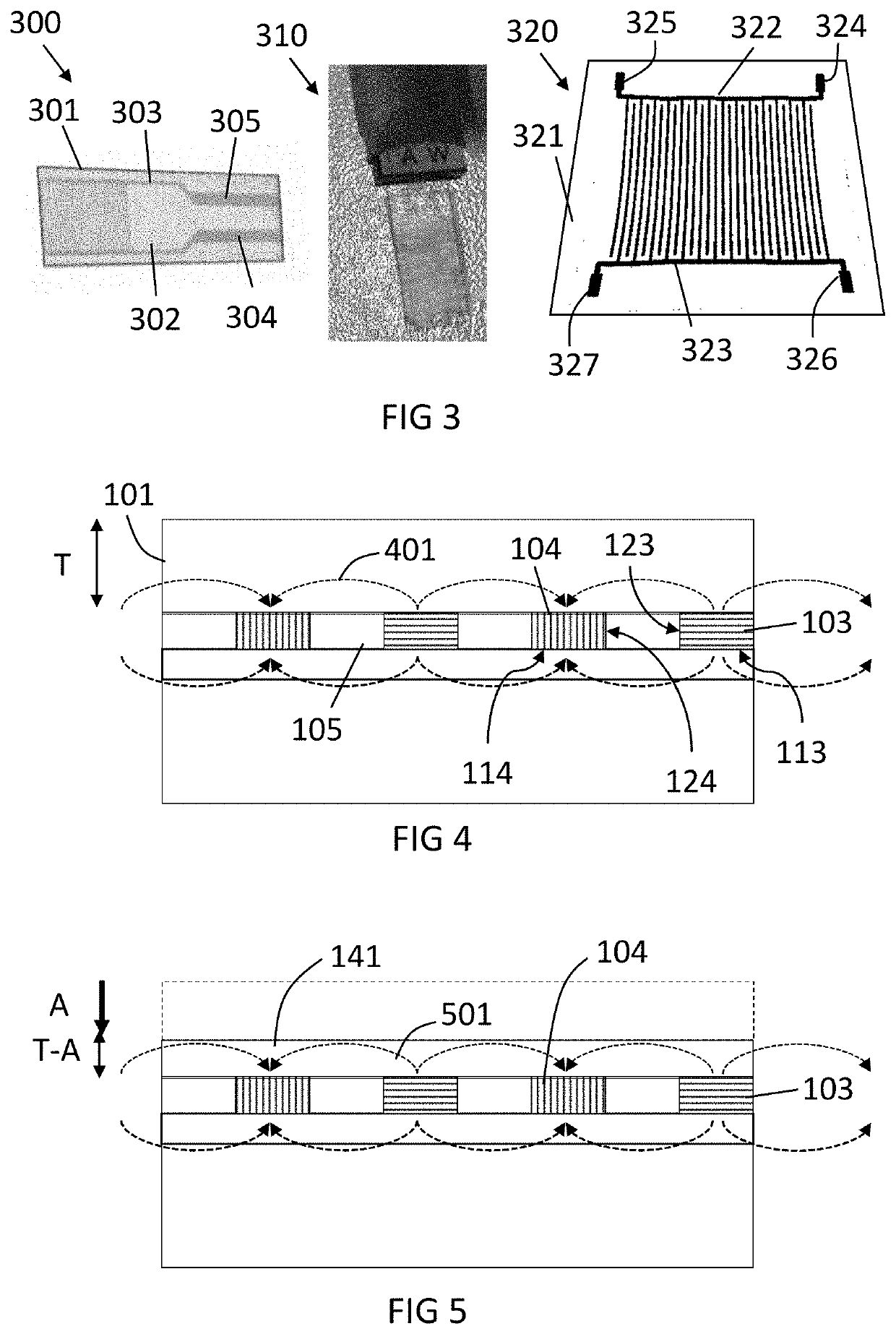
The present invention provides a system and sensor that can detect damage on a cover layer, even before the underlying structure is damaged. This results in better sensing capabilities.

Problems solved by technology

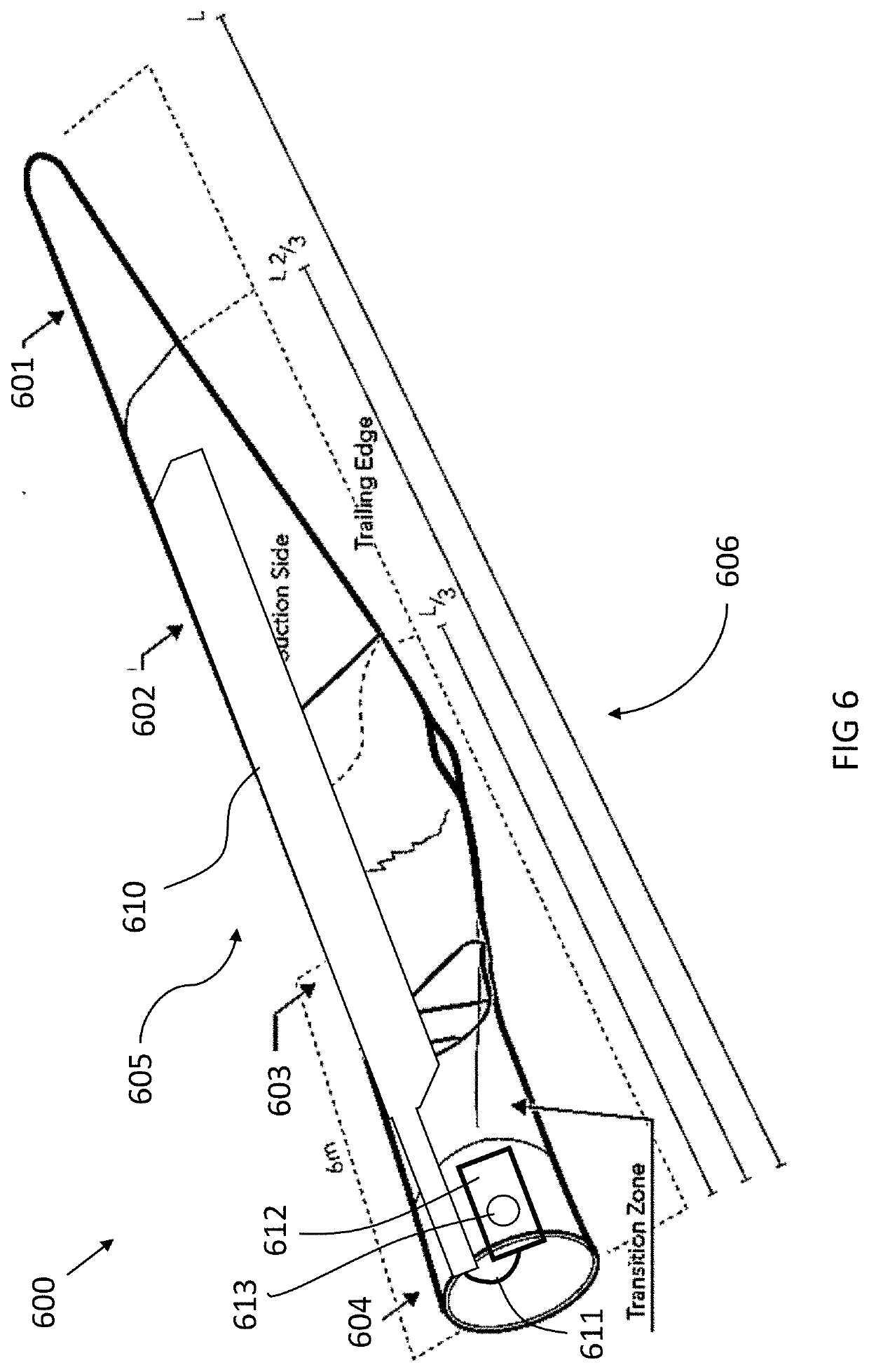
Mechanical structures such as turbines, ship hulls, beams, etc. are in contact with a surrounding environment which usually causes one or more types of mechanism that lead to failure of the structure, for example deformation or even rupture.
Examples of these mechanisms include abrasion, due to for example impacts with small particles of the environment with the structure, or erosion due to a combination of several mechanisms, with the same end result of material loss, causing damage to the structure.
Microdamages may also occur, for example due to pitting caused by chemical reaction of the surface of the structure with for example water droplets, and impacts thereof, leading to the formation of microscopic pores which may extend.
However, the protective layer at some point becomes also damaged due to exposure to the environment, and stops offering protection.
The protective layer thus needs to be replaced at a certain moment in time, but if the replacement is too early, then material is being wasted, and if it is too late, the damage in the structure may be extensive and reparations may be required.
However, these indications and alerts may appear too late, and the presence of these elements may affect the effectivity of the structure as well as their structural integrity.

Method used


Image

  • Smart sensing system
  • Smart sensing system
  • Smart sensing system

Examples


Embodiment Construction

[0056]The present invention will be described with respect to particular embodiments and with reference to certain drawings but the invention is not limited thereto but only by the claims. The dimensions and the relative dimensions do not correspond to actual reductions to practice of the invention.

[0057]Furthermore, the terms first, second and the like in the description and in the claims, are used for distinguishing between similar elements and not necessarily for describing a sequence, either temporally, spatially, in ranking or in any other manner. It is to be understood that the terms so used are interchangeable under appropriate circumstances and that the embodiments of the invention described herein are capable of operation in other sequences than described or illustrated herein.

[0058]Moreover, the terms top, under and the like in the description and the claims are used for descriptive purposes and not necessarily for describing relative positions. It is to be understood that...


PUM

PropertyMeasurementUnit
thicknessaaaaaaaaaa
thicknessaaaaaaaaaa
thicknessaaaaaaaaaa

Abstract

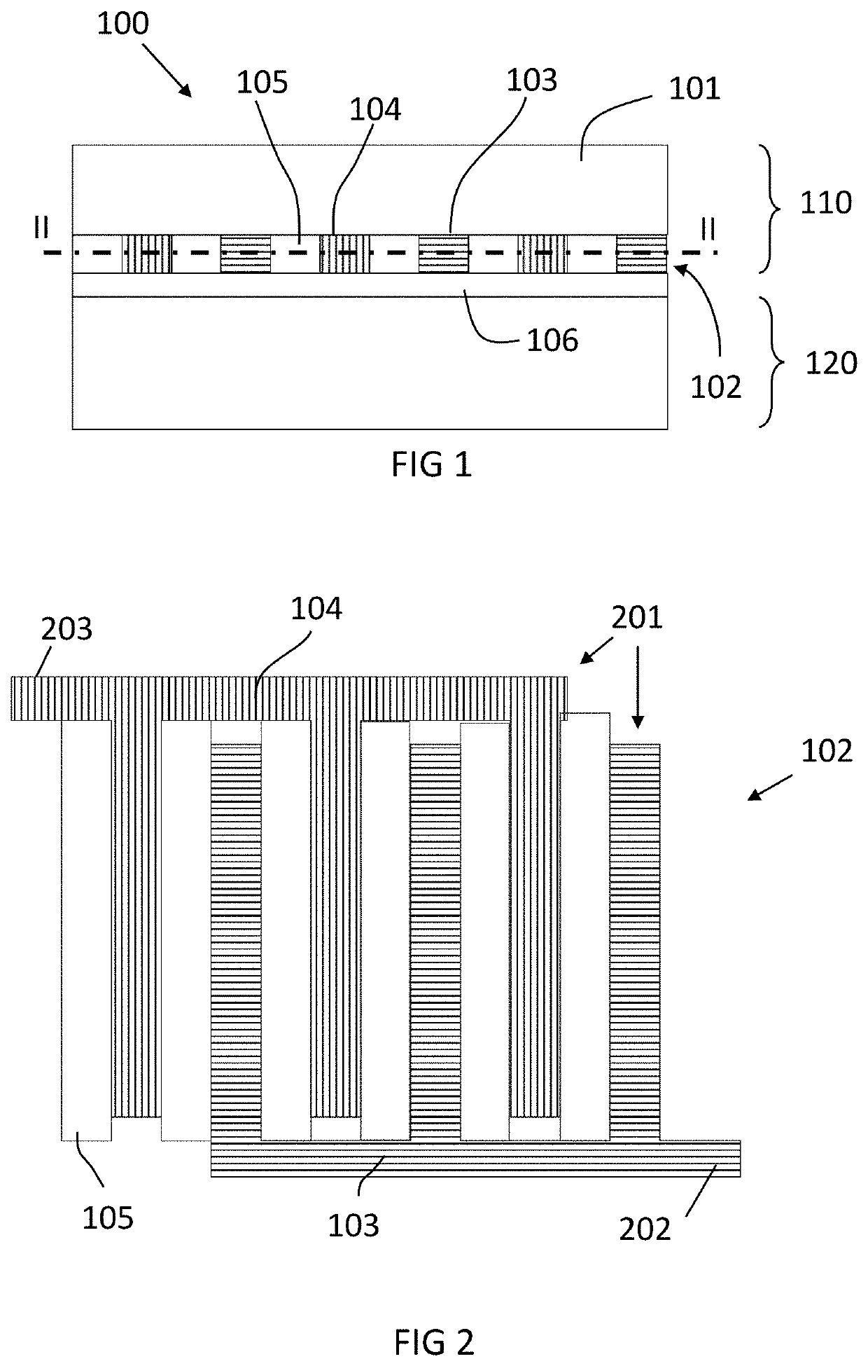
A sensing system including a cover layer for covering an underlying structure and at least a first electrode and at least a second electrode is described. The at least first and second electrodes are connectable to a signal source, for providing a signal coupling between the at least first and second electrodes, the at least first and second electrodes being isolated from each other. The at least first and second electrodes and the cover layer are configured so that the signal is at least partially transmitted through the cover layer, wherein the cover layer has an impedance, so that a change of the signal coupling between the at least first and at least second electrodes can be detected upon changes of impedance of the cover layer.

Description

FIELD OF THE INVENTION[0001]The invention relates to the field of sensing. More specifically it relates to systems and sensors for sensing material characteristics, e.g. for detecting erosion in engineering and transport structures.BACKGROUND OF THE INVENTION[0002]Mechanical structures such as turbines, ship hulls, beams, etc. are in contact with a surrounding environment which usually causes one or more types of mechanism that lead to failure of the structure, for example deformation or even rupture. Examples of these mechanisms include abrasion, due to for example impacts with small particles of the environment with the structure, or erosion due to a combination of several mechanisms, with the same end result of material loss, causing damage to the structure. Microdamages may also occur, for example due to pitting caused by chemical reaction of the surface of the structure with for example water droplets, and impacts thereof, leading to the formation of microscopic pores which may...

Claims


Application Information

Patent Timeline
Patent Type & Authority Applications(United States)
IPC IPC(8): G01N27/04G01N17/04
CPCG01N27/041G01N17/04G01N27/02F03D80/40
Inventor VAN INGELGEM, YVESPEETERS, BARTBIEGHS, PAUL
Owner ZENSOR NV
Learn More