
Engine Control Device and Engine Control Method

Active Publication Date: 2021-12-23
HITACHI ASTEMO LTD
View PDF0 Cites 0 Cited by
  • Summary
  • Abstract
  • Description
  • Claims
  • Application Information

AI Technical Summary

Benefits of technology

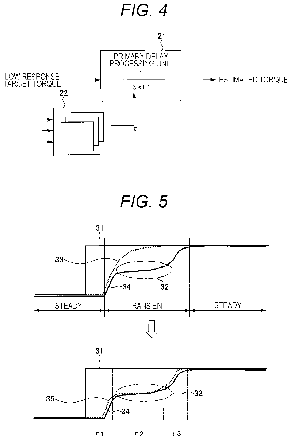
The present invention provides a method for controlling engines that have complicated torque patterns, such as turbo engines. This method doesn't require the time constant to be adjusted for optimal performance. This results in improved performance of these engines without the need for additional adjustments.

Problems solved by technology

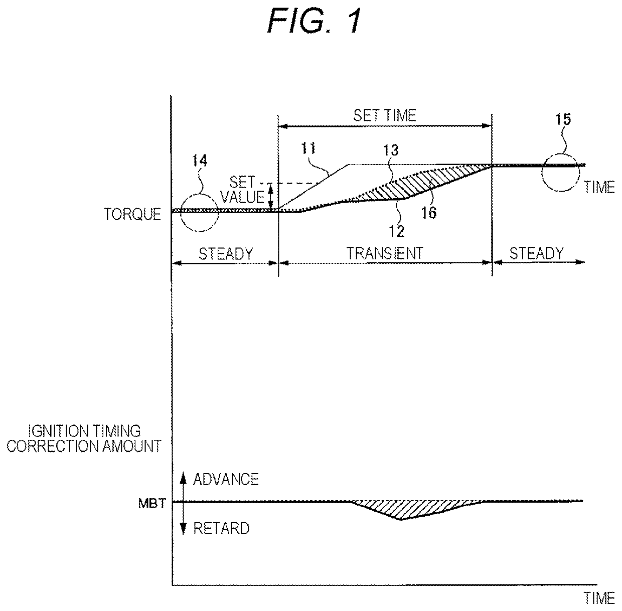
However, when the target torque changes in a complicated manner at high speed, it is difficult to generate the engine torque in accordance with the target torque by operating only the electronic control throttle due to a delay in the response of an intake air.
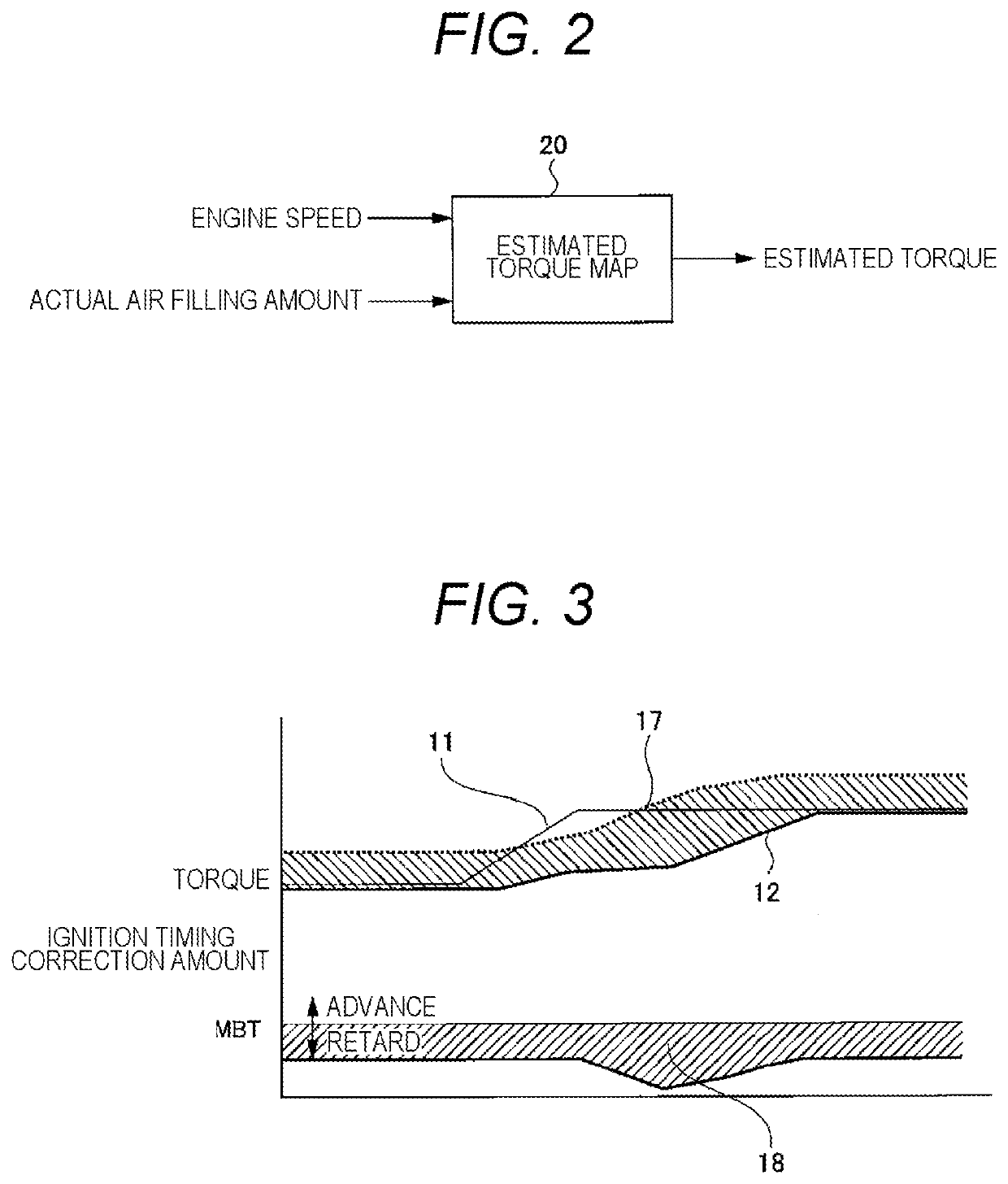
However, at present, since there is no device that directly measures the engine torque, it is necessary to estimate the actual generated torque when the low response torque control is implemented in order to implement both the low response torque control and the high response torque control.

Method used


Image

  • Engine Control Device and Engine Control Method
  • Engine Control Device and Engine Control Method
  • Engine Control Device and Engine Control Method

Examples


first embodiment

[0054]FIG. 6 is a schematic view illustrating a hardware configuration example of a torque-based engine system 1 compatible with a turbo engine to which an engine control device is applied according to a first embodiment. Hereinafter, a configuration example of the turbo engine compatible with the torque-based engine system 1 and a method of controlling an engine 10 (engine control method) will be described.

[0055]An engine 10 (an example of an internal combustion engine) is a turbocharged engine having a turbocharger 116. The engine (engine 10) performs torque-based engine control using the estimated torque. The estimated torque used in the torque-based engine control is calculated by an engine control unit (ECU) 102. An intake system of the engine 10 is provided with a compressor 117, which is a component of the turbocharger 116. An intake air compressed by the compressor 117 passes through an intake pipe 111 and is introduced to an inlet side of an electronic control throttle 107....

second embodiment

[0108]Next, a configuration example and an operation example of the estimated torque calculation unit according to the second embodiment will be described with reference to FIGS. 10 to 15.

[0109]First, an aspect in which the actual intake air amount vibrates in small steps will be described with reference to FIG. 13.

[0110]FIG. 13 is an explanatory diagram illustrating an aspect in which an actual intake air amount 321 vibrates with respect to a target intake air amount320.

[0111]In a transient state in which the actual intake air amount 321 changes toward the target intake air amount 320, the actual intake air amount 321 tends to vibrate as illustrated in FIG. 13. However, if the actual intake air amount 321 used for calculating the primary delay coefficient α is vibrating, the primary delay coefficient α may not be calculated appropriately.

[0112]In addition, the primary delay coefficient α calculated by the primary delay coefficient calculation unit 301 according to the first embodim...

third embodiment

[0146]Next, a configuration example and an operation example of an estimated torque calculation unit according to a third embodiment will be described with reference to FIGS. 16 to 19.

[0147]First, a point where the target intake air amount and the actual intake air amount are offset will be described with reference to FIG. 17.

[0148]FIG. 17 is an explanatory diagram illustrating an example in which a torque estimation error 343 occurs in a low response target torque 341 and estimated torque 342 due to an offset 333 between a target intake air amount 331 and an actual intake air amount 332.

[0149]An upper chart of FIG. 17 illustrates an aspect in which the offset 333 occurs between the target intake air amount 331 and the actual intake air amount 332. As described above, in the steady state, the target intake air amount 331 and the actual intake air amount 332 should coincide with each other. However, due to the influence of sensor error, environmental change, or the like, the offset 3...


PUM


Abstract

For an engine that draws a complicated torque trajectory, it has been taken a lot of time to adapt a time constant for calculation of estimated torque. Therefore, an ECU 102 includes a target torque calculation unit 203 that calculates target torque of an engine for which torque-based engine control is performed using estimated torque, and an estimated torque calculation unit 210 that calculates the estimated torque by calculating a primary delay coefficient 304 equivalent to a time constant calculated for each control cycle based on a change in an actual intake air amount with respect to a target intake air amount of air sucked into the engine and performing primary delay processing on the target torque using the primary delay coefficient 304.

Description

TECHNICAL FIELD[0001]The present invention relates to an engine control device and an engine control method for performing torque-based (torque demand) type engine control.BACKGROUND ART[0002]Torque-based (torque demand) engine control has been put into practical use as one of the control methods for an engine having an electronically controlled throttle (hereinafter abbreviated as “electronic control throttle”). The torque-based engine control is a control method capable of performing throttle control, fuel control, ignition control, and the like so as to calculate target torque of the engine based on an accelerator opening and an engine speed to achieve both the target torque and a target air-fuel ratio.[0003]Torque control in the torque-based engine control includes two types of low response torque control performed via an intake air amount operation represented by an electronic control throttle operation and high response throttle control performed without intake air amount oper...

Claims


Application Information

Patent Timeline
IPC IPC(8): F02D41/14F02D41/00F02D41/18F02P5/15
CPCF02D41/1401F02D41/0087F02D41/182F02D2200/1004F02D2041/1431F02D2041/1432F02P5/1504F02D2250/18F02D41/18F02D37/02F02D41/0007Y02T10/12Y02T10/40
Inventor ISHIKAWA, YOSHIMASASATO, SHINYA
Owner HITACHI ASTEMO LTD
Learn More