Multi-frequency tuning network system and method

a multi-frequency tuning and network technology, applied in the field of multi-frequency tuning network system and method, can solve the problem of difficulty in a transmitter antenna to transmit high power at multiple frequencies, and achieve the effect of effective circuit operation

Active Publication Date: 2021-12-30
BAKER HUGHES OILFIELD OPERATIONS LLC
View PDF3 Cites 0 Cited by
  • Summary
  • Abstract
  • Description
  • Claims
  • Application Information

AI Technical Summary

Benefits of technology

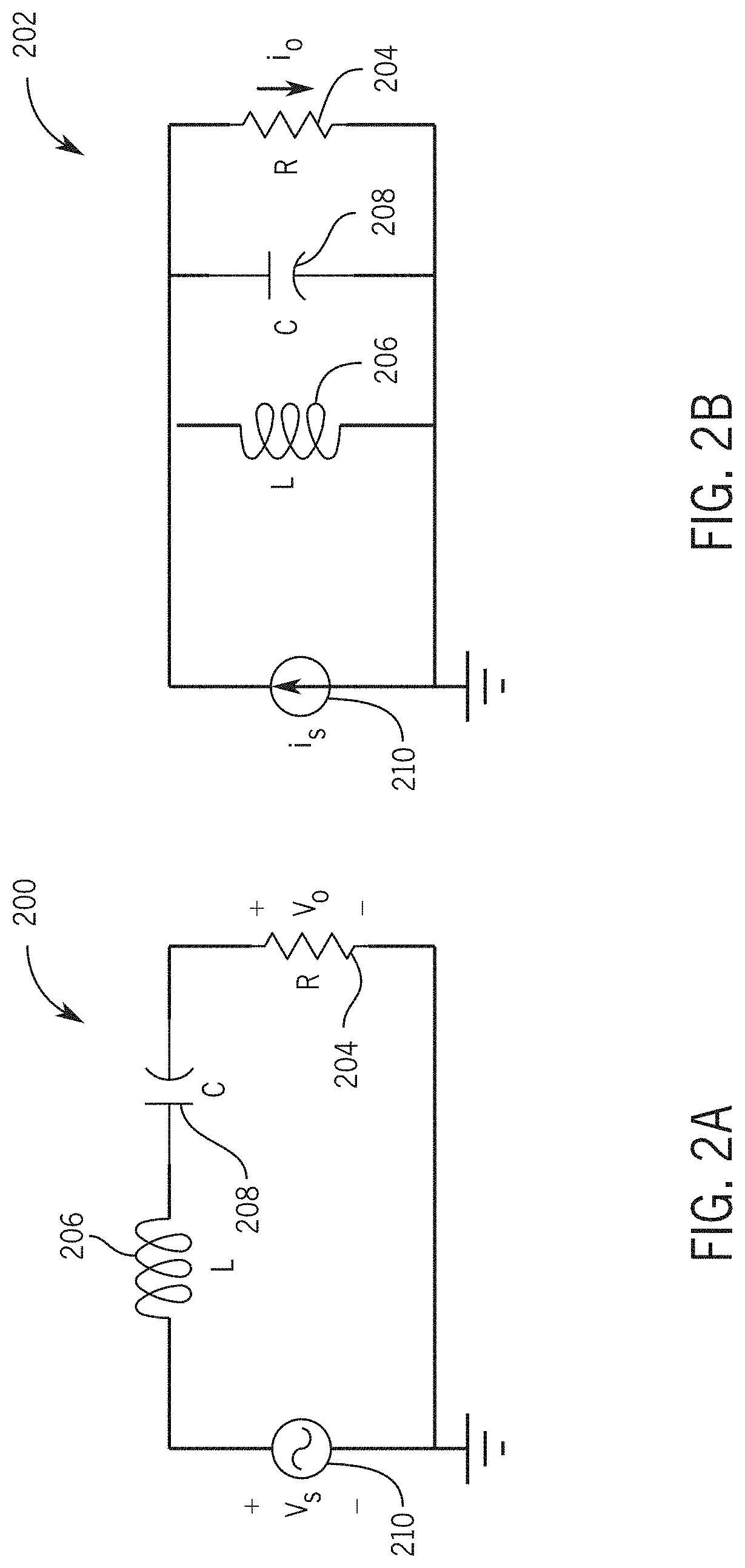
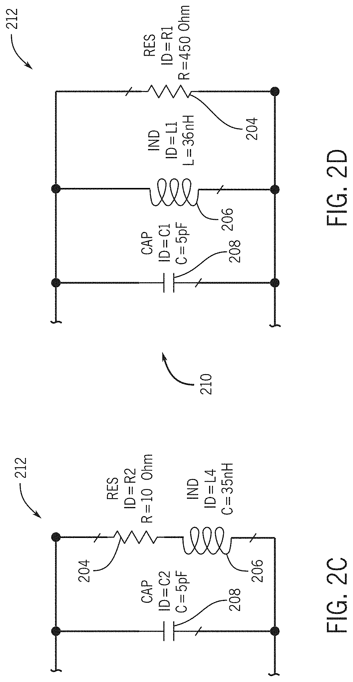
[0004]In an embodiment, a multi-frequency tuning circuit includes a first branch including a first inductor and a first capacitor arranged in series and a second branch including a second inductor and a second capacitor arranged in series. The circuit is arranged within a circuitry module configured to be positioned between a high frequency power source and an antenna, A source of high frequency electric power such as a generator, power amplifier, or transmitter has a source impedance which is equivalent to an electrical resistance in series with a reactance. An electrical load, such as an antenna, similarly has an impedance, which is typically equivalent to a resistance in series with a reactance. From the source point of view, the load input impedance is equal to the input impedance associated with the tuning circuit. The first branch and the second branch both associated with loads, from the source, have low impedances at first and second resonant frequencies respectively, where a high impedance can be created between them. Tuning the high impedance to a desired frequency, using embodiments of the present disclosure, enables effective operation of the circuit.

Problems solved by technology

Typically antenna load impedance is not equal to the source impedance, which makes it difficult for a transmitter antenna to transmit high power at multiple frequencies.

Method used


Image

  • Multi-frequency tuning network system and method
  • Multi-frequency tuning network system and method
  • Multi-frequency tuning network system and method

Examples


Embodiment Construction

[0022]The foregoing aspects, features, and advantages of the present disclosure will be further appreciated when considered with reference to the following description of embodiments and accompanying drawings. In describing the embodiments of the disclosure illustrated in the appended drawings, specific terminology will be used for the sake of clarity. However, the disclosure is not intended to be limited to the specific terms used, and it is to be understood that each specific term includes equivalents that operate in a similar manner to accomplish a similar purpose. Additionally, references numerals may be reused for similar features between figures, however, such use is not intended to be limiting and is for convenience and illustrative purposes only.

[0023]When introducing elements of various embodiments of the present disclosure, the articles “a”, “an”, “the”, and “said” are intended to mean that there are one or more of the elements. The terms “comprising”, “including”, and “ha...


PUM


Abstract

A multi-frequency tuning circuit includes a first branch including a first inductor and a first capacitor arranged in series and a second branch including a second inductor and a second capacitor arranged in series. The circuit is arranged within a circuitry module configured to be positioned between a source and a load, the first branch and the second branch both associated with loads, from the source, having low impedance frequencies. In order to improve transmitter antenna output power for downhole tools, the tuning circuit creates high impedance at operating frequencies between frequencies corresponding to low impedance.

Description

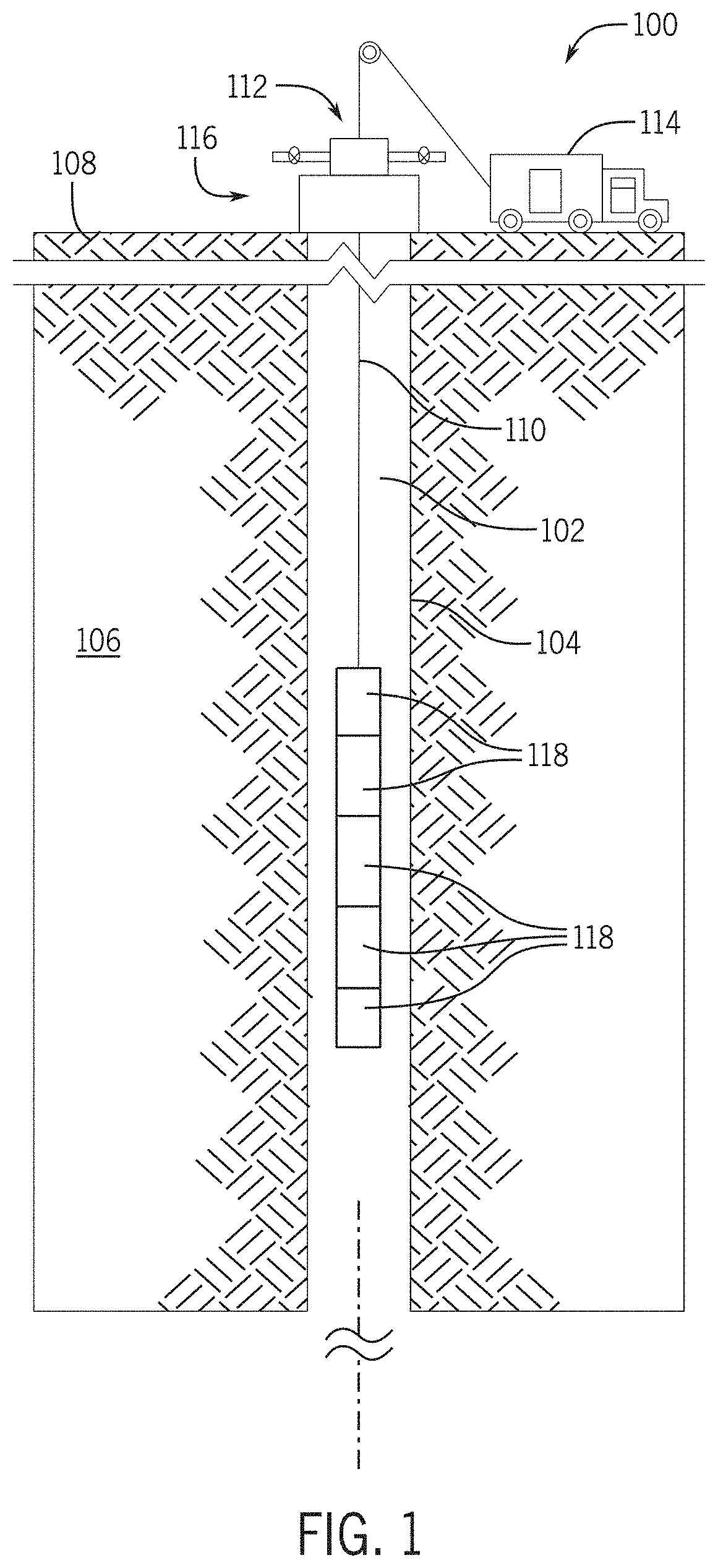
BACKGROUND1. Field of the Disclosure[0001]The present disclosure relates to a system and method for tuning and / or adjusting power output for a tool, such as a downhole logging tool. More specifically, the present disclosure is directed towards systems and methods for determining and creating high impedances at desired frequencies to improve transmitter antenna output power for downhole tools.2. Description of Related Art[0002]Oil and gas production may involve downhole measurement operations where various sensors are utilized to collect data for determining one or more wellbore properties. In dielectric services, one or multiple transmitter antennas are used to generate transmit signals in form of electromagnetic waves generated in radio frequencies, and receiver antennas are used to detect these signals, which propagate through downhole formations. The transmitter and receiver antennas are typically of induction type with a radiation pattern close to the radiation pattern of magnet...

Claims


Application Information

Patent Timeline
Patent Type & Authority Applications(United States)
IPC IPC(8): G01V3/30E21B47/12H03J3/22H01Q9/04
CPCG01V3/30H01Q9/04H03J3/22E21B47/12H01Q1/04H01Q5/50H03J3/28G01V3/32H01Q5/335H03H7/38
Inventor LIU, YIFORGANG, STANISLAV WILHELMJONES, JOHNRIVERO, CARLOSPEREZ, LOUISLE, FEIKOUCHMESHKY, BABAKZHANG, YINXI
Owner BAKER HUGHES OILFIELD OPERATIONS LLC
Why Eureka
Try Eureka