Display device

Active Publication Date: 2021-12-30
WUHAN CHINA STAR OPTOELECTRONICS TECH CO LTD
View PDF0 Cites 3 Cited by
  • Summary
  • Abstract
  • Description
  • Claims
  • Application Information

AI Technical Summary

Benefits of technology

[0047]The functional layers on the display panel are provided with the functional region arranged corresponding to the camera module. The functional region includes the light transmissive region arranged corresponding to the first hole and the light shielding region arranged around the light transmissive region. The light shielding region is arranged corresponding to the light shielding member in the backlight module, and the light shielding region shields the light shielding member. Such configuration improves a problem that an aperture of an opening region of an under-screen camera deforms due to the light shielding member.
[0048]In order to more clearly illustrate the embodiments of t

Problems solved by technology

However, due to a lack of coating precision of the light shielding adhesive and the interference with adhesive layers at edges of the opening of a backlight plate, the light shieldin

Method used


Image

  • Display device
  • Display device

Examples


Example

First Embodiment

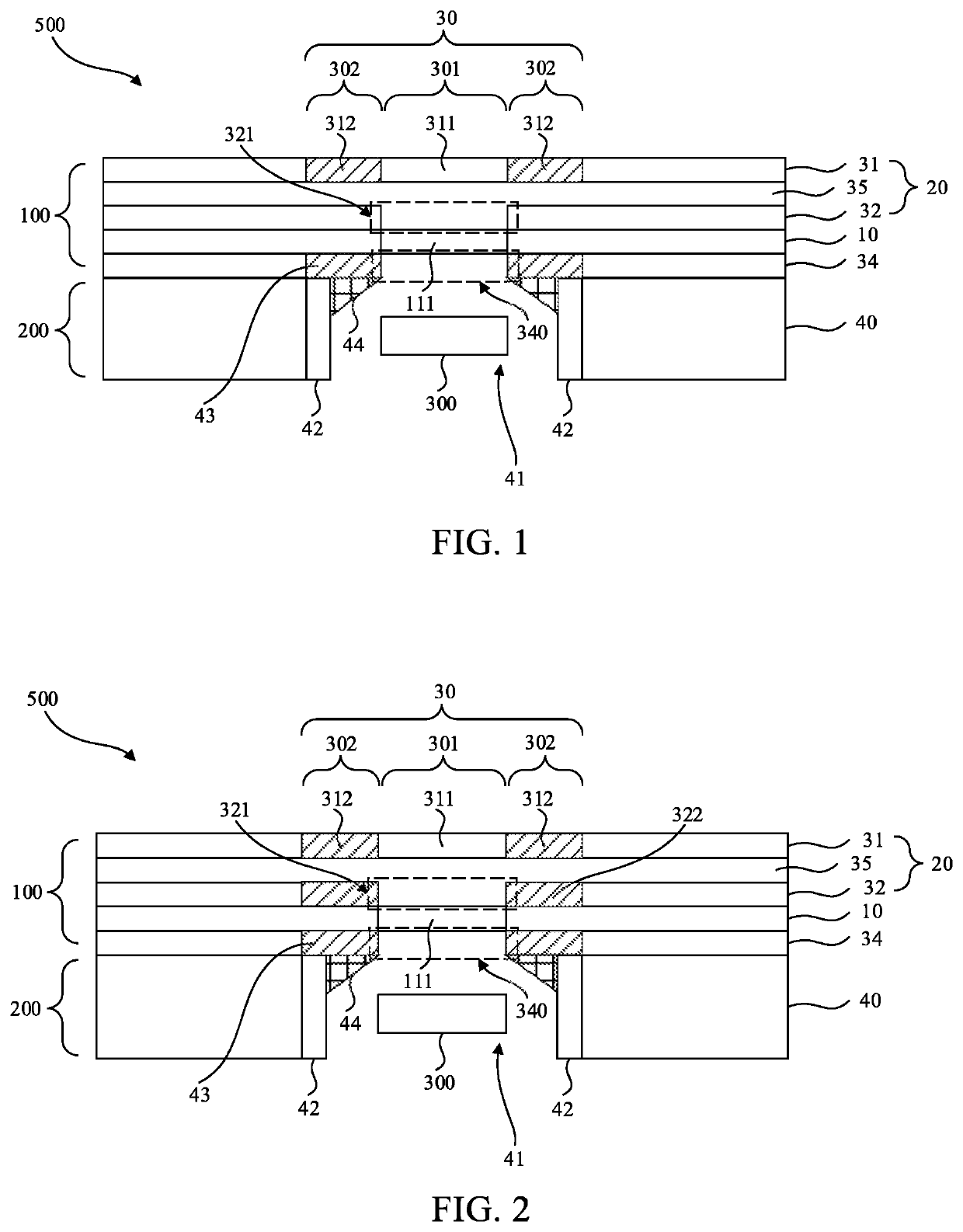
[0064]Referring to FIG. 1, the display module 100 includes an upper polarizer layer 32 on the display panel 10 and a cover layer 31 on the upper polarizer layer 32.

[0065]In the present embodiment, the cover layer 31 comprises a first functional region disposed corresponding to the camera module 300. The first functional region 30 comprises a first light transmissive region 311 arranged corresponding to the first hole 111 and a first light shielding region 312 arranged around the first light transmissive region 311.

[0066]According to the present embodiment, the first light shielding region 312 is made of one of ink, a black photoresist material, and a light-shielding metal.

[0067]According to the present embodiment, the first light shielding region 312 has a ring shape.

[0068]According to the present embodiment, the polarizer layer 32 comprises a second hole 321 disposed corresponding to the first light transmissive region 311. The first hole 111 is a blind hole, and th...

Example

Second Embodiment

[0080]Referring to FIG. 2, the present embodiment is the same as or similar to the first embodiment, except for a difference that:

[0081]The upper polarizer layer 32 further includes a second light shielding region 322 arranged corresponding to the first light shielding region 312.

[0082]In the present embodiment, the second light shielding region 322 is disposed around the second hole 321, and an orthographic projection of the second light shielding region 322 projected onto the cover layer 31 is in the first light shielding region 312.

[0083]In the present embodiment, the second light shielding region 322 and the first light shielding region 312 can be made of the same material. The second light shielding region 322 and the first light shielding region 312 can have a same shape and a same size.

[0084]In the present embodiment, the upper polarizer layer 32 is provided with the second hole 321 disposed corresponding to the first light transmissive region 311 and the sec...

Example

Third Embodiment

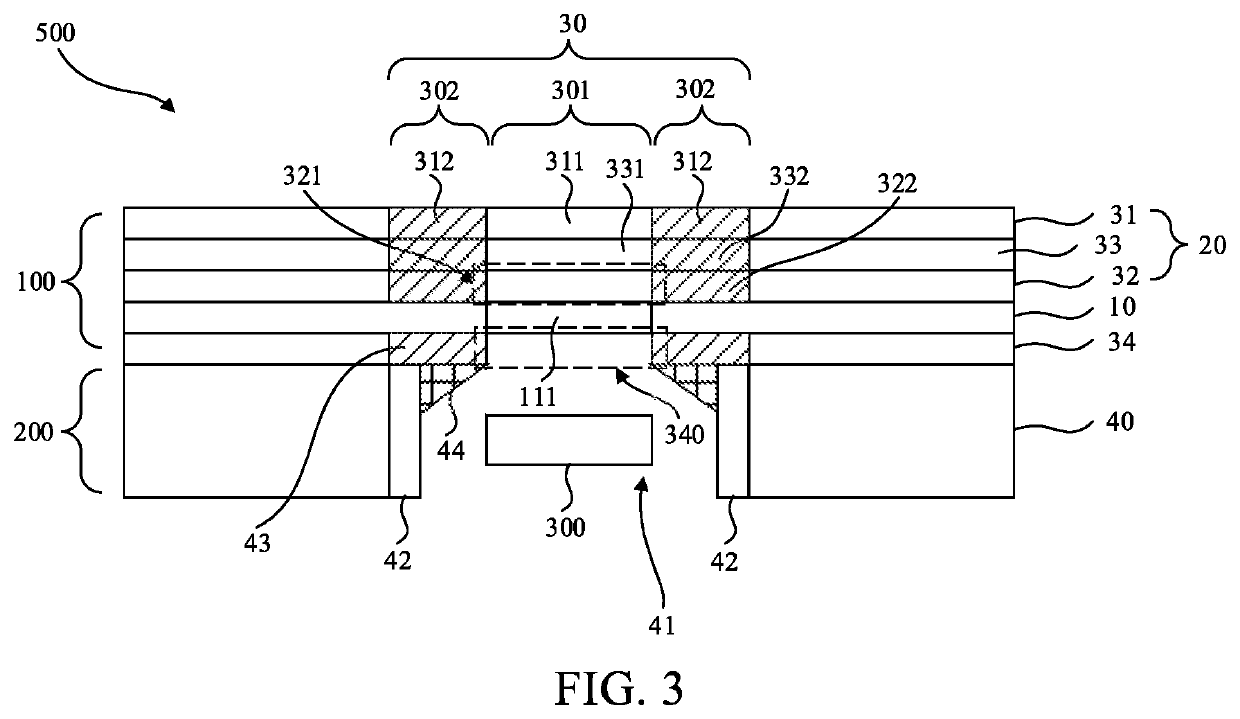
[0086]Referring to FIG. 3, the third embodiment is the same as or similar to the first embodiment and the second embodiment, except for a difference that: the functional layers 20 further comprise a touch layer 33 disposed between the cover layer 31 and the display panel 10.

[0087]The touch layer 33 may be disposed between the upper polarizer layer 32 and the cover layer 31, or between the display panel 10 and the upper polarizer layer 32, or embedded in the cover layer 31. The position of the touch layer 33 is not limited in this embodiment.

[0088]In the present embodiment, the touch layer 33 comprises a third hole 331 and a third light shielding region 332. The third hole 331 is disposed corresponding to the first hole 111, and the third light shielding region 332 is arranged around the third hole 331 and disposed corresponding to the first light shielding region 312.

[0089]In the present embodiment, the third hole 331 can be a through hole.

[0090]In the present embodi...


PUM


Abstract

The present invention provides a display device. Multiple functional layers on a display panel are provided with a functional region arranged corresponding to a camera module. The functional region includes a light transmissive region arranged corresponding to a first hole and a light shielding region arranged around the light transmissive region. The light shielding region is arranged corresponding to the light shielding member in a backlight module, and the light shielding region shields a light shielding member. Such configuration improves a problem that an aperture of an opening region of an under-screen camera deforms due to the light shielding member.

Description

FIELD AND BACKGROUND OF THE INVENTION[0001]The present invention relates to a field of display devices and in particular, to a display device.[0002]With development of liquid crystal display technology, especially for full-screen designs, most manufacturers install in a display device a backlight module with an opening facing inward, so that an under-screen camera can be placed in the opening to receive ambient light.[0003]In conventional display devices, when the under-screen camera is disposed under the opening of the backlight module of the display device, the opening will only serve as a channel for the under-screen camera to receive ambient light. In order to prevent the backlight module's backlight source from interfering with the opening, the light shielding adhesive is often applied at a gap between a lower polarizer and a display panel and at a boundary between an opening region and the backlight source. However, due to a lack of coating precision of the light shielding adh...

Claims


Application Information

Patent Timeline
IPC IPC(8): G02F1/13357G02F1/1335G02F1/1333H04N5/225G03B29/00
CPCG02F1/133602G02F1/133512H04N5/2257G02F1/133528G02F1/133331G02F1/1333G03B29/00G02F1/133615H04N23/57H04N23/55G02F1/13338
Inventor YU, PENGFEI
Owner WUHAN CHINA STAR OPTOELECTRONICS TECH CO LTD
Why Eureka
Try Eureka