
Display panel and manufacturing method thereof

a technology of display panel and manufacturing method, which is applied in the field of display panel, can solve the problems of how to improve the transmittance at a fixed aperture ratio, and achieve the effects of reducing color resistivity, improving transmittance, and effective improvemen

Active Publication Date: 2021-12-30
TCL CHINA STAR OPTOELECTRONICS TECH CO LTD
View PDF1 Cites 0 Cited by
  • Summary
  • Abstract
  • Description
  • Claims
  • Application Information

AI Technical Summary

Benefits of technology

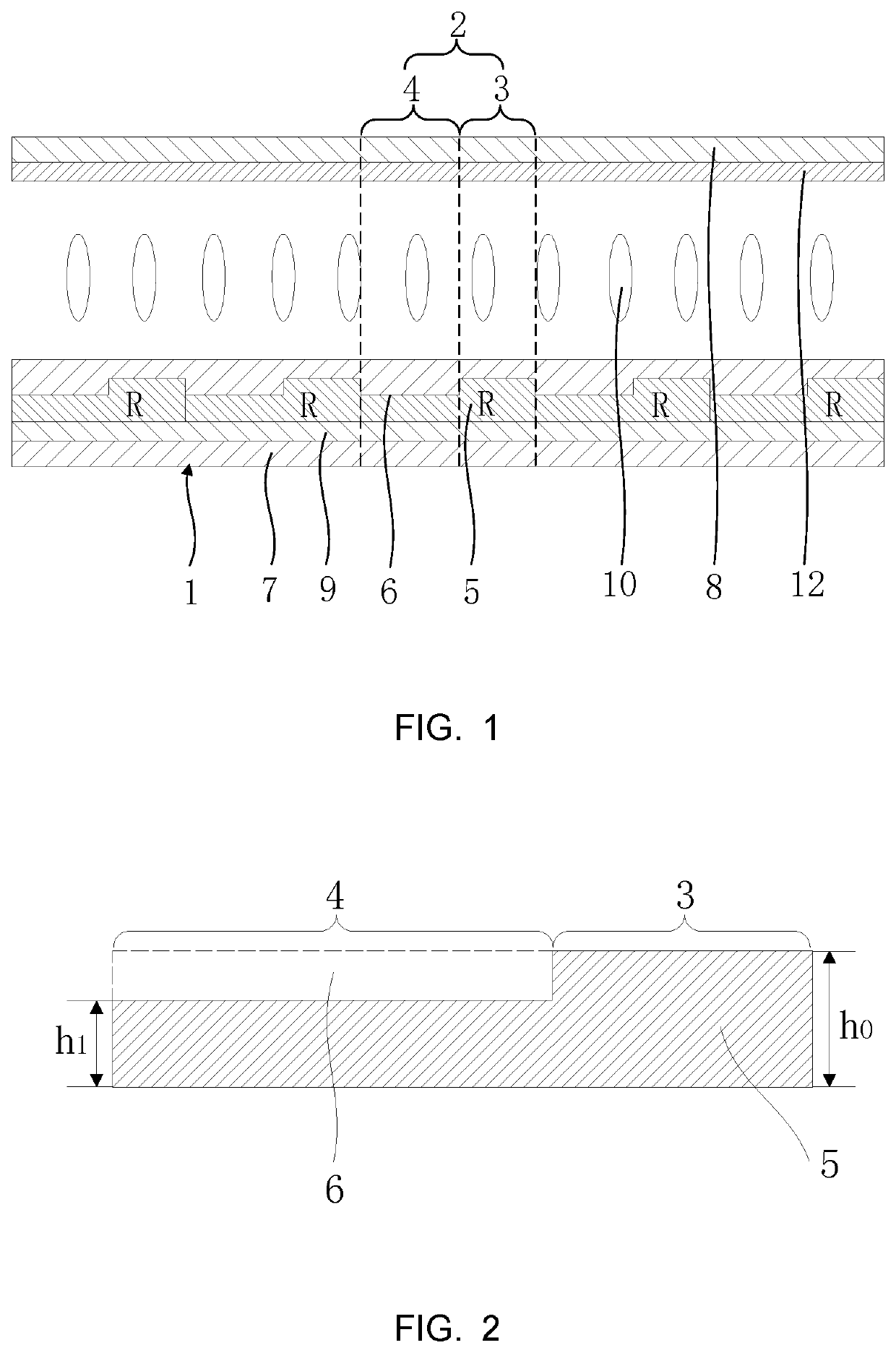
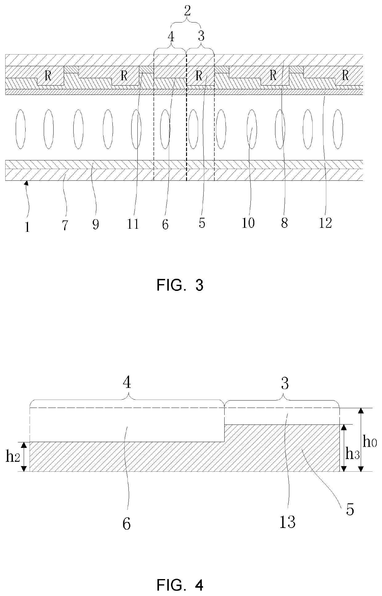
The present invention provides a display panel with improved transmittance by reducing the thickness of the color resist in a secondary pixel region on a basis of ensuring that brightness of the secondary pixel region is less than a brightness of a primary pixel region. This can effectively improve the overall transmittance of the display panel without changing an area size of each sub-pixel region, and can also relieve the problem of color shift caused by thinning color resist. In simple terms, this invention allows for a thinner and more transparent display panel with improved color accuracy.

Problems solved by technology

How to improve transmittance at a fixed aperture ratio has become a problem for the display panel industry.

Method used


Image

  • Display panel and manufacturing method thereof
  • Display panel and manufacturing method thereof
  • Display panel and manufacturing method thereof

Examples


Embodiment Construction

[0040]The technical solution in the embodiments of the present invention will be clearly and completely described below with reference to the accompanying drawings in the embodiments of the present invention. It is to be understood that the described embodiments are merely exemplary of the invention, and not restrictive of the full scope of the invention. All other embodiments, which can be obtained by a person skilled in the art without inventive step based on the embodiments of the present invention, are within the scope of the present invention.

[0041]In the description of the present invention, it is to be understood that the terms “center,”“longitudinal,”“lateral,”“length,”“width,”“thickness,”“upper,”“lower,”“front,”“rear,”“left,”“right,”“vertical,”“horizontal,”“top,”“bottom,”“inner,”“outer,”“clockwise,”“counterclockwise,” and the like are used in the orientations and positional relationships indicated in the drawings for convenience in describing the present invention and for s...


PUM

PropertyMeasurementUnit
thicknessaaaaaaaaaa
brightnessaaaaaaaaaa
heightaaaaaaaaaa

Abstract

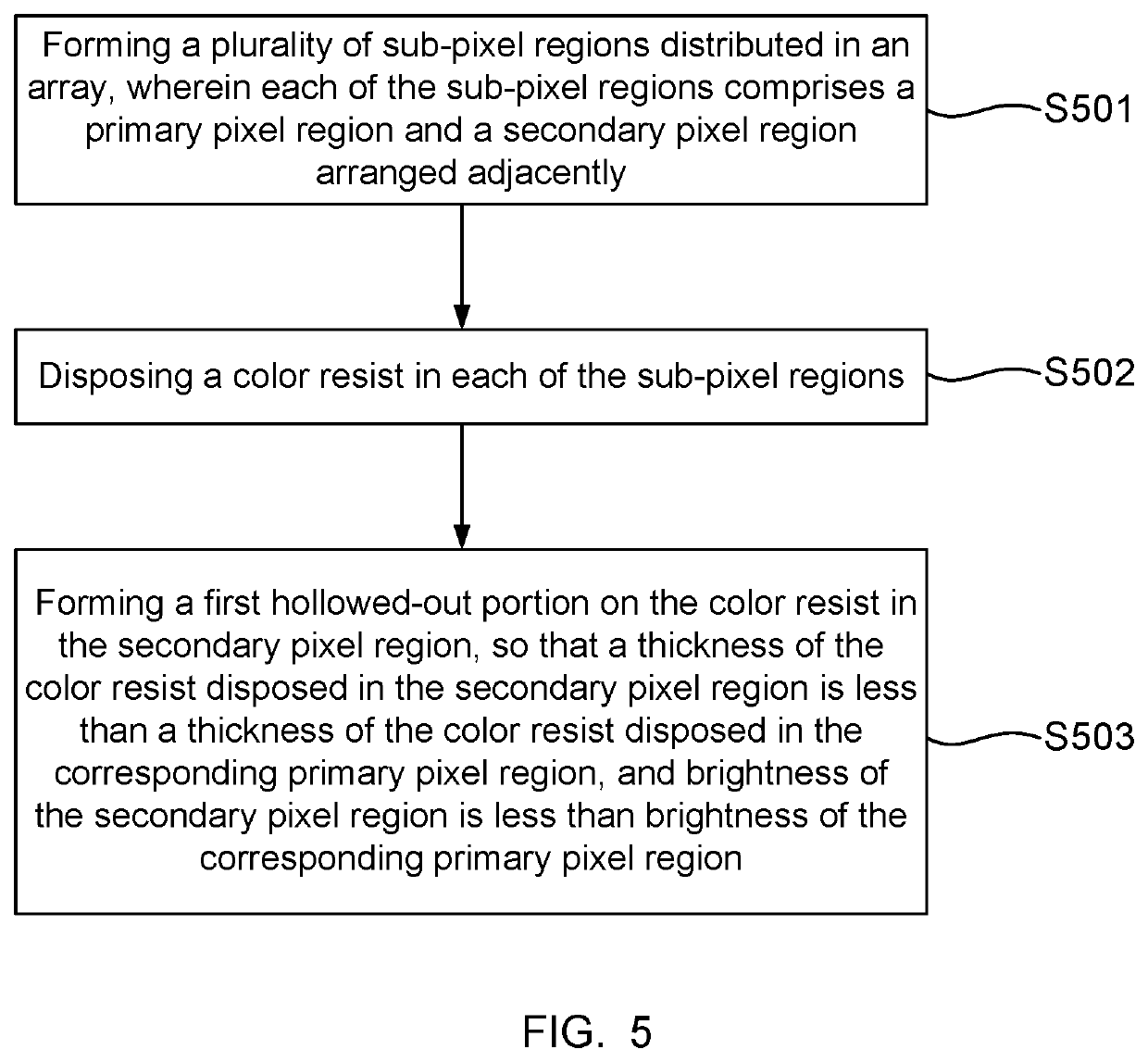
The present invention provides a display panel and a manufacturing method Thereof. The display panel includes a plurality of sub-pixel regions distributed in an array. Each of the sub-pixel regions includes a primary pixel region and a secondary pixel region arranged adjacently. Each of the sub-pixel regions is provided with a color resist. The color resist disposed in the secondary pixel region is provided with a first hollowed-out portion, so that a thickness of the color resist disposed in the secondary pixel region is less than a thickness of the color resist disposed in the corresponding primary pixel region, and brightness of the secondary pixel region is less than brightness of the corresponding primary pixel region.

Description

CROSS REFERENCE TO RELATED APPLICATIONS[0001]This application claims priority to Chinese patent application No. 202010004221.1, titled “Display Panel and Manufacturing Method Thereof” in Chinese Priority Patent Application, filed on Jan. 3, 2020 with the National Intellectual Property Administration, which is incorporated by reference in the present application in its entirety.FIELD OF INVENTION[0002]The present invention relates to the field of display panels, and in particular, to a display panel and a manufacturing method thereof.BACKGROUND OF INVENTION[0003]Liquid crystal displays (LCDs) are widely used flat-panel displays, which mainly use switches of liquid crystals to modulate light field intensity of backlight sources to achieve displays.[0004]With development of display technologies, requirements for resolution of display panels are becoming increasingly higher. As resolution increases, transmittance will decrease, which will affect display effect. How to improve transmitta...

Claims


Application Information

Patent Timeline
Patent Type & Authority Applications(United States)
IPC IPC(8): G02F1/1362G02F1/1368
CPCG02F1/136222G02F1/1368G02F1/133514G02F1/133516
Inventor TANG, HANTING
Owner TCL CHINA STAR OPTOELECTRONICS TECH CO LTD
Learn More