Splice and patch panel GUI for cable layout and design

a technology of patch panel and cable layout, which is applied in the direction of electronic network arrangement, instruments, computing, etc., can solve the problems of inability to keep track of all cables, tubes, fibers, interconnections or splices between fibers, and the difficulty of program success, and achieves convenient drilling, efficient layout of splices, and greater level of detail

Pending Publication Date: 2021-12-30
IQGEO AMERICA INC
View PDF2 Cites 0 Cited by
  • Summary
  • Abstract
  • Description
  • Claims
  • Application Information

AI Technical Summary

Benefits of technology

[0010]The present invention is directed to a system and method for managing fiber optic networks, including defining, modifying, and visualizing a network topology and connections between fiber optic elements. A computer-based tool is provided for automating several processes that are presently time-consuming and labor intensive projects, and more specifically, for enabling a user to view and illustrate in a graphical manner the splices between individual fibers in multiple tubes within multiple cables. Moreover, a user may dynamically move one or more optical elements in the schematic diagram and the computer-based tool will automatically redraw and store all of the splices between fibers in a manner that creates an efficient layout of the splices. The schematic diagram may show different levels of detail and thereby hide specific splices between fibers until needed and allows a user to easily drill down to show greater levels of detail in the schematic diagram as needed. In this manner, the invention facilitates effective visualization and management of fiber networks.

Problems solved by technology

However, the ability to keep track of all the cables, the tubes, the fibers and the interconnections or splices between fibers has also become exponentially more difficult.
However, these programs have had limited success because they are cumbersome to use and do not provide an easy way to illustrate connections.
The problem of illustration connections through schematic diagrams is also exacerbated when connections are changed, thus rendering the existing schematic diagrams obsolete.
Furthermore, updating existing schematic diagrams has been a laborious and time-consuming task that existing tools have failed to make less cumbersome.
Finally, adding, subtracting, or moving entire cables from the schematic diagrams is equally time consuming and labor intensive.

Method used


Image

  • Splice and patch panel GUI for cable layout and design
  • Splice and patch panel GUI for cable layout and design
  • Splice and patch panel GUI for cable layout and design

Examples


first embodiment

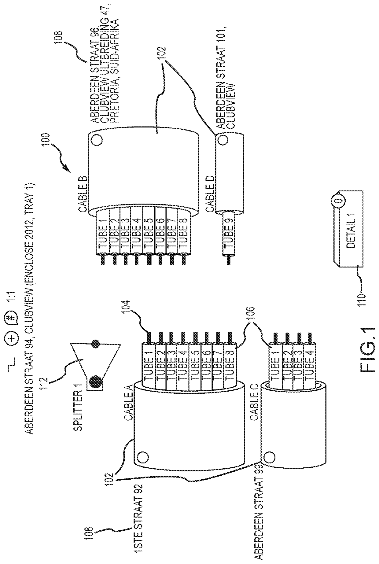
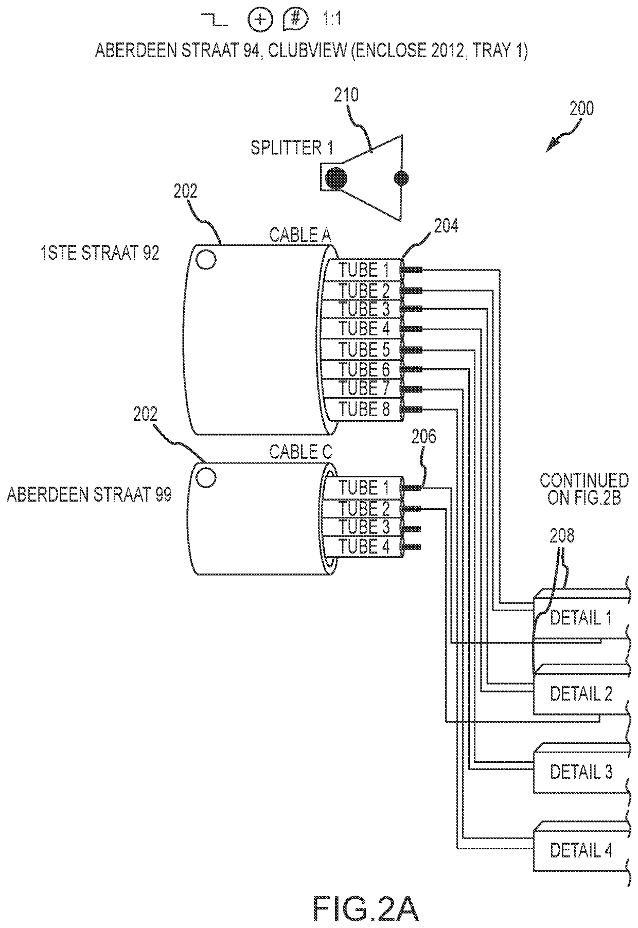
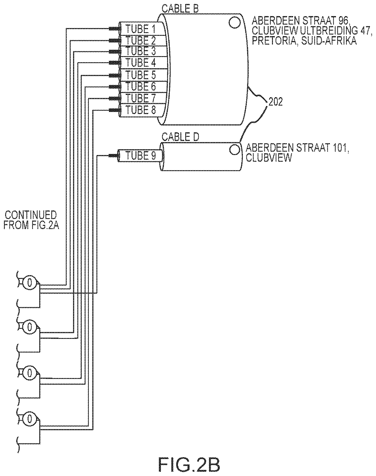
[0072]FIG. 1 is an illustration of a user interface 100 of a computer-based tool in accordance with the invention. The interface 100 shows a number of optical elements that are brought together at connection or splice point of an optical network. The optical elements may be brought together at a physical splicing enclosure such as a splice box or cabinet. The optical elements include cables 102 that carry either fibers 104 or tubes 106 within the cables 102 that contain the fibers 104. Accordingly, whatever structure of fibers 106 that exists within cables 102 may be illustrated by the computer-based tool of the present invention. The various tubes 106 and fibers 104 may be labeled with letters, numbers and colors to distinguish and assist in identifying them to the user.

[0073]FIG. 1 also shows that each of the cables 102 may include a label 108 that identifies where each of the cables 102 is coming from. The labels 108 may include street numbers, physical splicing locations, juncti...

second embodiment

[0096]In the invention, the computer-based tool may be modified to illustrate patch panels. Patch panels may often be disposed near computer servers and telephone switches and allow connections to be made and easily changed between various devices coupled to the patch panels as is known to those skilled in the art. In this regard, an optical element such as an optical fiber may have terminals that can be plugged into ports or receptacles on a patch panel. However, the maze of patch cables may easily obscure connections and make them difficult to trace.

[0097]Patch panels come in a variety of configurations relating to the number and arrangement of ports on a faceplate of the panel. In order to facilitate rapidly creating a graphical face plate, the user may first input certain parameters. These parameters may include the number of columns, the number of rows, and the number of ports per column. Thus, a user interface may be provided that allows a user to specify values for each of th...

third embodiment

[0110]the invention is described in relation to FIGS. 19-27. FIG. 19 is a bird's-eye view diagram 1900 of a street map with a manhole cover 1902 and duct banks 1904 superimposed thereon.

[0111]FIG. 20 is a modified view of FIG. 19 which now shows graphics 2000 that indicate the super ducts and inner ducts within each of the duct banks.

[0112]FIG. 21 show a butterfly drawing 2100 of the third embodiment of the invention. The butterfly drawing 2100 lays out the fiber elements 2102 of the duct banks 2104 of each wall of the manhole. In this case, there are four walls so there are four walls shown relative to each other. Each of the walls shows the cross-section of the duct 2104 that enters the manhole, and the direction from which the ducts enter.

[0113]FIG. 22 shows butterfly drawing 2200 that may be rendered automatically using a database of information. The drawing 2200 shows detail views 2202 that may be displayed, for example, for each of the ducts that enters a manhole upon selectin...


PUM


Abstract

The present invention is a system and method for automating several processes that are presently time-consuming and labor intensive projects, and more specifically, the invention is a system and method implemented by a computer-based tool that enables a user to bring multiple cables (202) together and illustrate in a graphical manner the splices between individual fibers (206) in multiple tubes (204) within multiple cables (202). In addition, user may dynamically move one of more cables (202) in the schematic diagram (200) and the tool will automatically redraw all of the splices between fibers (202) in a manner that creates an efficient layout of the splices. The schematic diagram (200) may show different levels of detail and thereby hide specific splices between fibers (206) until they are needed.

Description

CROSS-REFERENCE TO RELATED APPLICATION[0001]This application claims priority to U.S. Provisional Patent Application No. 63 / 036,690 entitled “SPLICE AND PATCH PANEL GUI FOR CABLE LAYOUT AND DESIGN” filed Jun. 9, 2020. The contents of the above-noted provisional application is incorporated herein as if set forth in full and priority to this application is claimed to the full extent allowable under U.S. law and regulations.BACKGROUNDField of the Invention[0002]This invention relates generally to a computer-based tool for automated layout and modification of connections between optical elements of a fiber optic network. More specifically, the invention relates to a system and method for automating the illustration of connections between individual optical elements and enabling modifications of those connections.Description of Related Art[0003]The tracking of connections between fiber optic cables and the fiber optic tubes and optical fibers within the cables is critically important in f...

Claims


Application Information

Patent Timeline
Patent Type & Authority Applications(United States)
IPC IPC(8): G06F3/0484G06F3/0482
CPCG06F3/0484G06F3/0482H04Q2011/0079H04B10/27H04L41/12H04L41/22
Inventor ANDERSON, RANDALL S.
Owner IQGEO AMERICA INC
Why Eureka
Try Eureka