

Ball joint
a ball joint and ball bearing technology, applied in the field of ball bearing joints, can solve the problems of reducing the operational performance of the joint, and achieve the effect of improving the operational performance and the joint performan
- Summary
- Abstract
- Description
- Claims
- Application Information
AI Technical Summary
Benefits of technology
Problems solved by technology
Method used
Image

Examples
Embodiment Construction
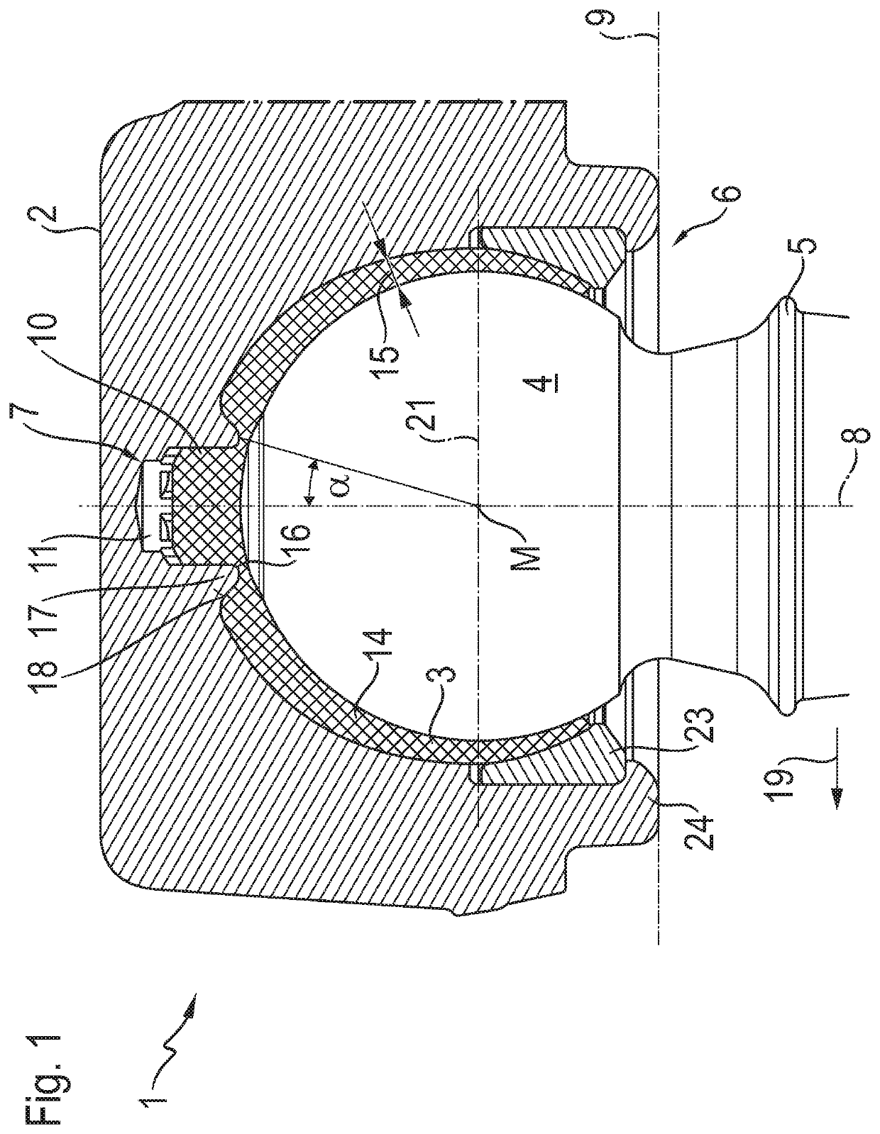
[0021]FIG. 1 shows a specific design of the ball joint 1 in the assembled condition, with a housing 2, a ball socket 3 and a joint ball 4 fitted therein, which extends through the ball socket 2 with a shank 5 at a joint aperture 6. The ball socket 3 is connected to the housing 2 by anti-rotation means 7, which prevent any movement of the ball socket 3 within the housing 2, in particular any rotation about the central longitudinal axis 8 (vertical axis), which is arranged perpendicularly to a plane 9 of the joint aperture 6 or the equator 21 of the ball socket 3 and passes through the mid-point M of the ball socket 3. In the example embodiment shown, the anti-rotation means 7 consists of a connecting element 10 on the ball socket 3, which is designed as a positive shape, and a correspondingly designed connecting element 11 of the housing 2, which is designed as a negative shape. Both connecting elements are of cylindrical design and, on their respective cylindrical outer and cylindri...
PUM
 Abstract
Description
Claims
Application Information