Reacting device of dual path synchronous immunochromatographic platform and it's using method
- Summary
- Abstract
- Description
- Claims
- Application Information
AI Technical Summary
Benefits of technology
Problems solved by technology
Method used
Image

Examples
Embodiment Construction
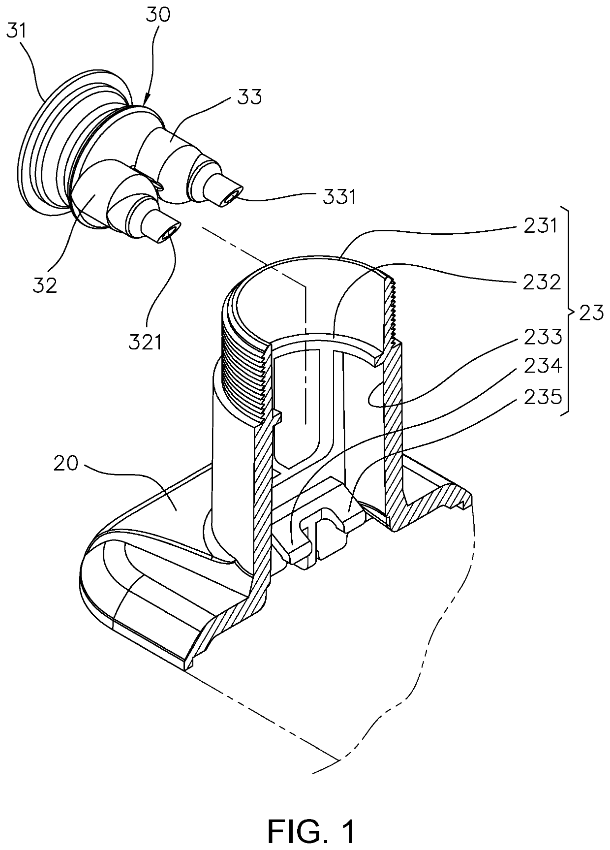
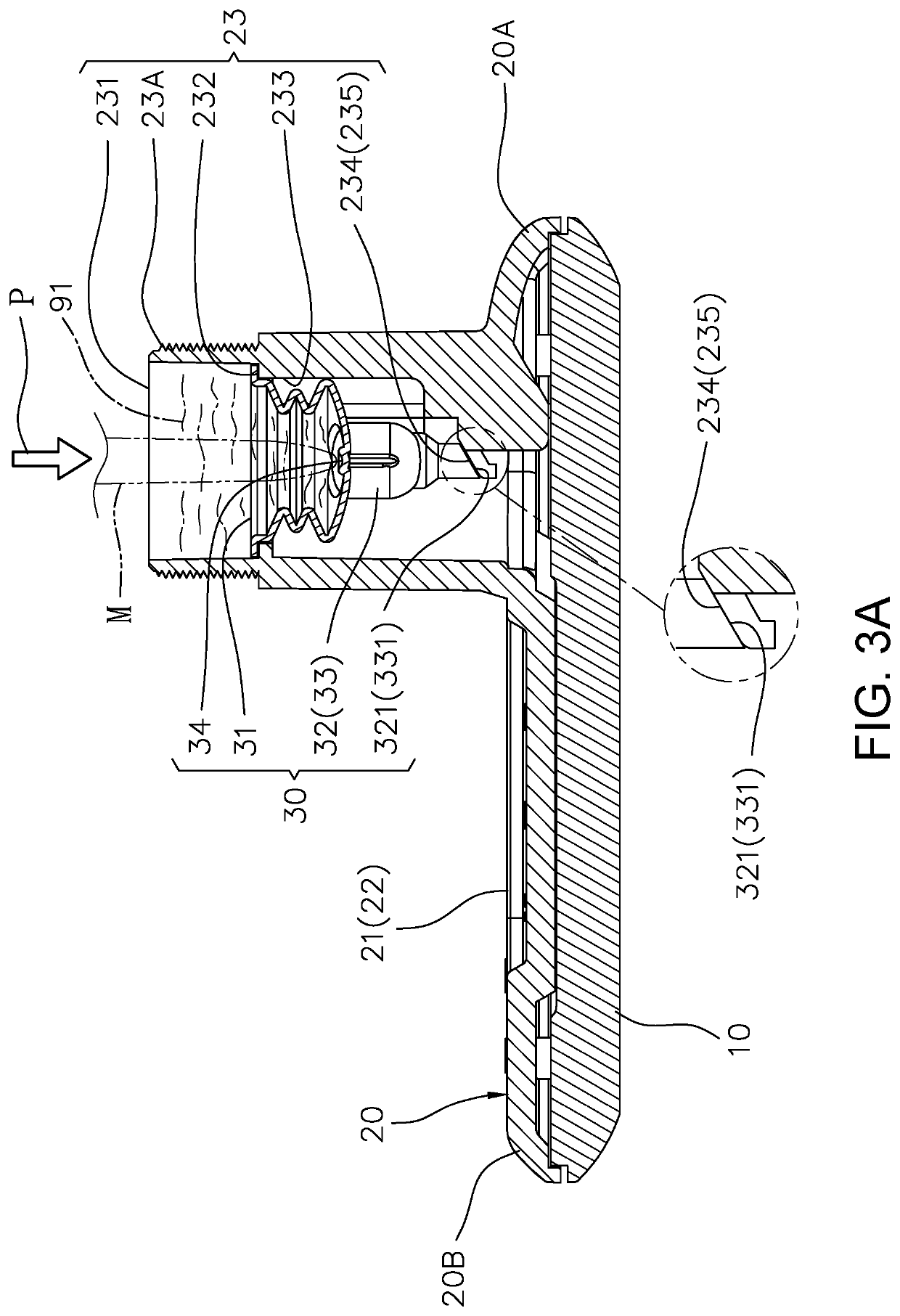
[0035]FIGS. 1, 2, 3A, 3B, 3C, 3D, 3E, and 4 illustrate an exemplary embodiment of this invention. This invention relates to a reacting device of dual path synchronous immunochromatographic platform and it's using method. About the reacting device, it mainly includes a base 10, an upper housing 20, and a fluid dividing funnel 30.
[0036]With regard to this seat 10, it has a first slot 11 and a second slot 12. The first slot 11 is provided for receiving a first immunochromatographic carrier T1. The second slot 12 is provided for receiving a second immunochromatographic carrier T2.
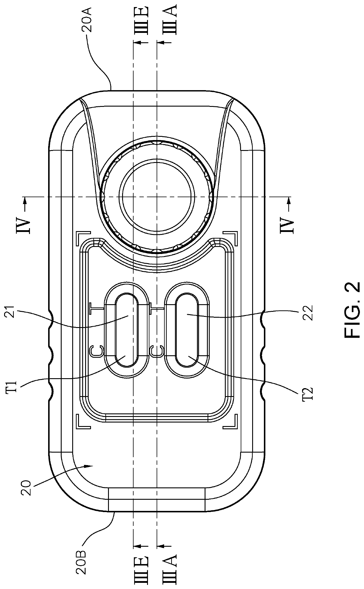
[0037]About this upper housing 20, it is disposed on the seat 10. The upper housing includes a first window 21, a second window 22, a hollow pipe portion 23, a first end 20A, and a second end 20B. The first window 21, the second window 22, and the hollow pipe portion 23 are positioned between the first end 20A and the second end 20B. The first window 21 is disposed on the first slot 11. The second window 22 is ...
PUM
 Abstract
Description
Claims
Application Information
 - R&D
- Intellectual Property
- Life Sciences
- Materials
- Tech Scout
- Unparalleled Data Quality
- Higher Quality Content
- 60% Fewer Hallucinations
Browse by: Latest US Patents, China's latest patents, Technical Efficacy Thesaurus, Application Domain, Technology Topic, Popular Technical Reports.
© 2025 PatSnap. All rights reserved.Legal|Privacy policy|Modern Slavery Act Transparency Statement|Sitemap|About US| Contact US: help@patsnap.com