Working machine

a technology of working machine and inching valve, which is applied in mechanical machines/dredgers, braking systems, braking components, etc., can solve the problems of large space and difficulty in arranging the inching valve directly under the pedal, and achieve the effect of improving ventilation, improving flexibility of the mounting position of the inching valve, and facilitating cleaning of the floor par

Pending Publication Date: 2022-01-20
KUBOTA LTD
View PDF0 Cites 0 Cited by
  • Summary
  • Abstract
  • Description
  • Claims
  • Application Information

AI Technical Summary

Benefits of technology

[0033]According to the working machine as mentioned above, by operably connecting the pedal and the inching valve with the cable, the flexibility of the mounting position of the inching valve can be improved. In addition, by attaching the pedal and the inching valve to the floor frame supported by the machine body via a mounting member, that is, to the same vibration system, the inching valve can be suppressed from being affected by traveling vibrations and working vibrations.
[0034]In addition, according to the working machine as mentioned above, by providing the entrance passage on one side portion of the operator's seat and providing an opening part on the other side portion, the advantages of improved ventilation and easy cleaning work of the floor part can be provided. In addition, the blocking member can prevent an operator from boarding and alighting through the opening part that is provided opposite to the entrance passage.
[0035]In addition, according to the working machine mentioned above, a filter can be shared for the inside-air and for the outside-air by providing adjacent to each other the inside-air / outside-air switching portion and the filter housing portion, the inside-air / outside-air switching portion being configured to be switched between a state in which the outside-air is introduced and a state in which the outside-air is not introduced, and the filter housing portion being configured to house the filter that removes dusts from the inside-air and the outside-air flowing from the inside-air / outside-air switching portion to the air-conditioner main unit. In addition, since the inside-air introducing port, the outside-air introducing port, and the switching damper are provided in one place, the inside-air / outside-air switching portion can be compactly formed.

Problems solved by technology

However, depending on a supporting structure of the pedal, it may be difficult to arrange the inching valve directly under the pedal due to space constraints.
In addition, a large space is required to install an inside-air / outside-air switching portion that is switched between the inside-air introducing state and the outside-air introducing state.

Method used


Image

  • Working machine
  • Working machine
  • Working machine

Examples


Embodiment Construction

[0062]The preferred embodiments will now be described with reference to the accompanying drawings, wherein like reference numerals designate corresponding or identical elements throughout the various drawings. The drawings are to be viewed in an orientation in which the reference numerals are viewed correctly.

[0063]With appropriate reference to the drawings, an embodiment of the present invention will be described below.

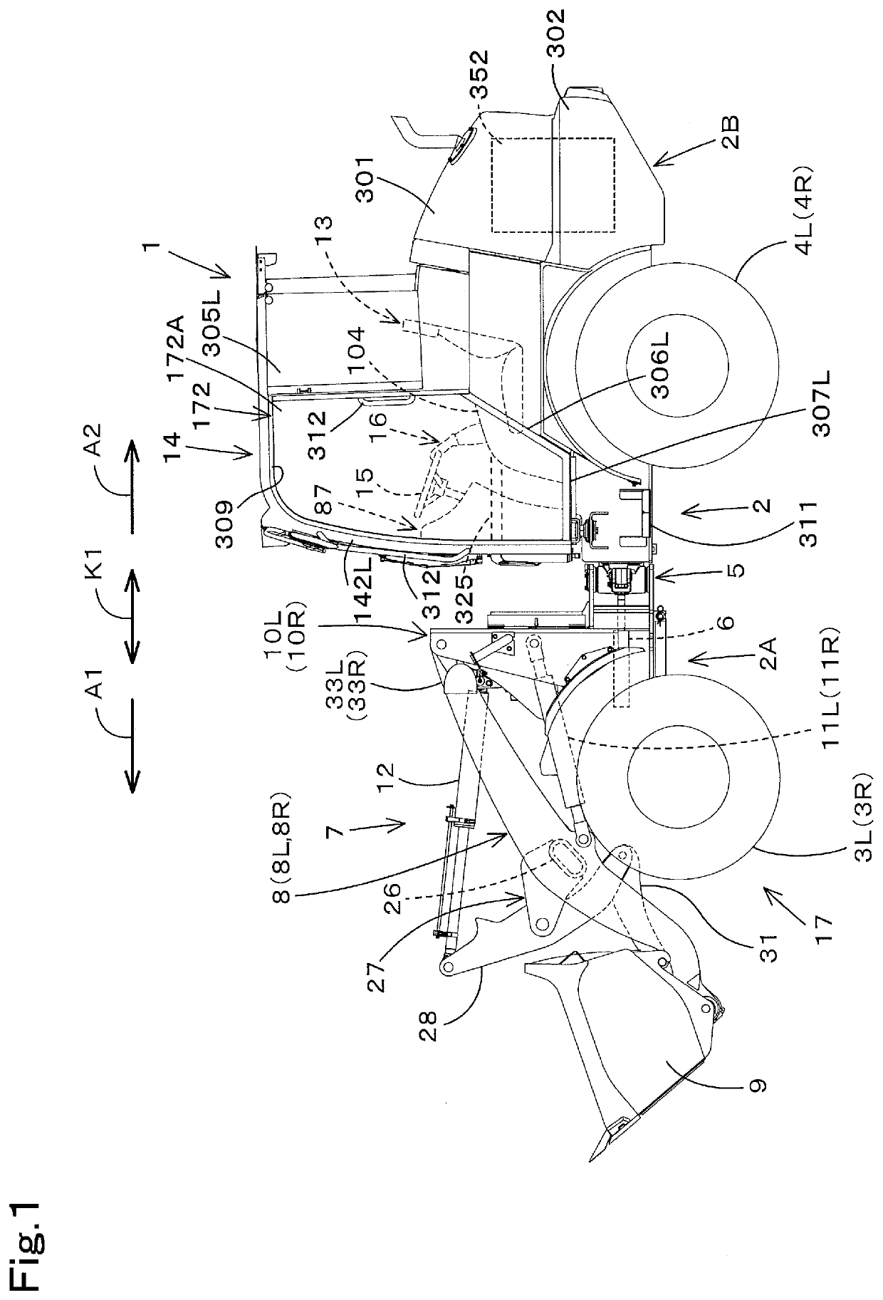
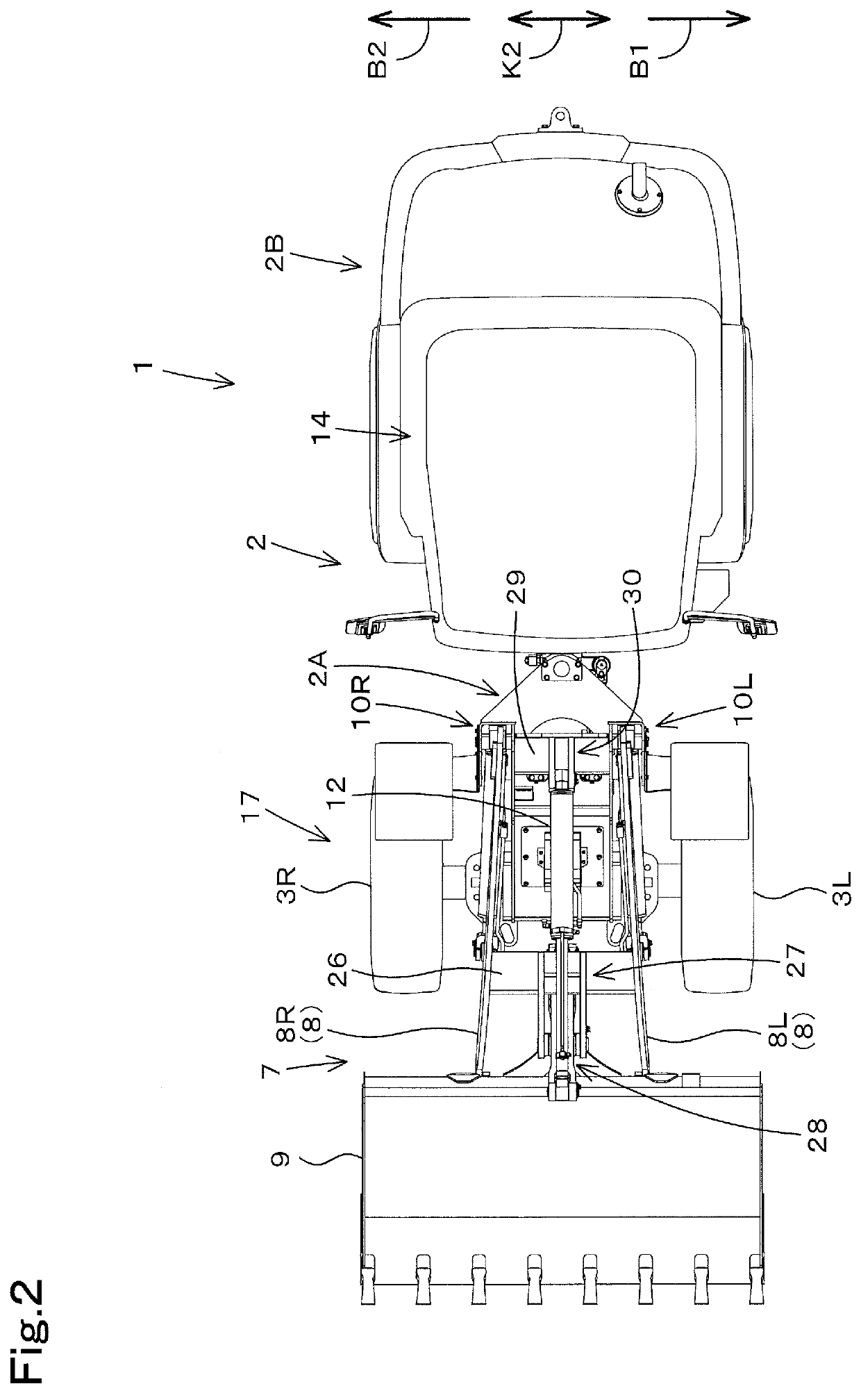
[0064]FIG. 1 is a schematic side view showing an overall configuration of a working machine 1 according to the present embodiment. FIG. 2 is a schematic plan view of the working machine 1. In the present embodiment, a wheel loader is exemplified as the working machine 1.

[0065]As shown in FIGS. 1 and 2, a wheel loader according to the present embodiment is an articulated working machine 1, and a machine body 2 of the working machine 1 includes a front machine body 2A and a rear machine body 2B. The front machine body 2A is provided with a left front wheel 3L and a rig...


PUM


Abstract

A working machine includes a machine body, a traveling device travelably supporting the machine body, a hydraulic driving device to hydraulically drive the traveling device, a floor frame supported on the machine body via a mounting member, a pedal operable to brake the traveling device, the inching valve to change a flow rate of hydraulic fluid supplied to the hydraulic driving device according to operation of the pedal, and a cable operably connecting the pedal to the inching valve. The pedal and the inching valve are attached to the floor frame.

Description

CROSS REFERENCE TO RELATED APPLICATIONS[0001]This application is a continuation application of International Application No. PCT / JP2019 / 050913, filed on Dec. 25, 2019, which claims the benefit of priority to Japanese Patent Application No. 2019-066394, filed on Mar. 29, 2019, and to Japanese Patent Application No. 2019-066396, filed on Mar. 29, 2019, and to Japanese Patent Application No. 2019-066399, filed on Mar. 29, 2019. The entire contents of each of these applications are hereby incorporated herein by reference.BACKGROUND OF THE INVENTIONField of the Invention[0002]The present invention relates to a working machine such as a wheel loader.Description of the Related Art[0003]Working machines disclosed in Japanese Unexamined Patent Application Publication No. 2012-224213, Japanese Unexamined Patent Application Publication No. 2019-7227, Japanese Unexamined Patent Application Publication No. 2012-144190 are known.[0004]The working machine disclosed in Japanese Unexamined Patent Ap...

Claims


Application Information

Patent Timeline
Patent Type & Authority Applications(United States)
IPC IPC(8): E02F3/36E02F3/38E02F3/43
CPCE02F3/3663E02F3/431E02F3/384E02F9/16B62D11/08B60T15/04E02F9/0841E02F3/3411E02F9/0833E02F9/0875E02F9/2004E02F9/2253
Inventor TAKANO, YUKIAIZAWA, TSUTOMUMATSUSHITA, TETSUJI
Owner KUBOTA LTD
Why Eureka
Try Eureka