Vehicle door lock apparatus

a technology for vehicle doors and locks, applied in the field of door locks, can solve the problems of increased number of required parts, increased manufacturing costs, and inflexible brackets, and achieve the effect of increasing the flexibility of the mounting angle of the key cylinder and increasing the flexibility of the mounting angl

Inactive Publication Date: 2005-09-06
AISIN SEIKI KK
View PDF24 Cites 32 Cited by
  • Summary
  • Abstract
  • Description
  • Claims
  • Application Information

AI Technical Summary

Benefits of technology

[0010]The input shaft of the lever mechanism directly connected with the key cylinder is inclinable relative to the output shaft of the lever mechanism. The inclination of the rotation shaft or axis of the key cylinder can be absorbed between the input shaft and the output shaft of the lever mechanism, this increasing the flexibility of the mounting angle. The inclination of the input shaft relative to the output shaft of the lever mechanism can be absorbed through the connection between the key rotor and the key lever. The inclination of the input shaft relative to the output shaft of the lever mechanism can thus be absorbed in an easy manner by virtue of the play between the key rotor-side engaging device of the key rotor and the key lever-side engaging device of the key lever.
[0011]The locating devices are formed at the key rotor and the key lever for locating the rotation fulcrum of the key rotor. Thus, the connection between the key rotor and the key lever, which is configured so that the inclination of the input shaft relative to the output shaft of the lever mechanism can be absorbed, is prevented from falling off.
[0012]The rotation shaft of the key cylinder is capable of being inclined relative to that of the key rotor. Thus, the inclination of the rotation shaft or axis of the key cylinder can be further absorbed and the flexibility of the mounting angle of the key cylinder can be further increased.

Problems solved by technology

Accordingly, the brackets are not versatile and the number of required parts is increased, as is the manufacturing cost, according to the number of different bracket types.
With this approach, flexibility associated with the mounting angle (rotation shaft direction) is significantly restricted.

Method used


Image

  • Vehicle door lock apparatus
  • Vehicle door lock apparatus
  • Vehicle door lock apparatus

Examples


Embodiment Construction

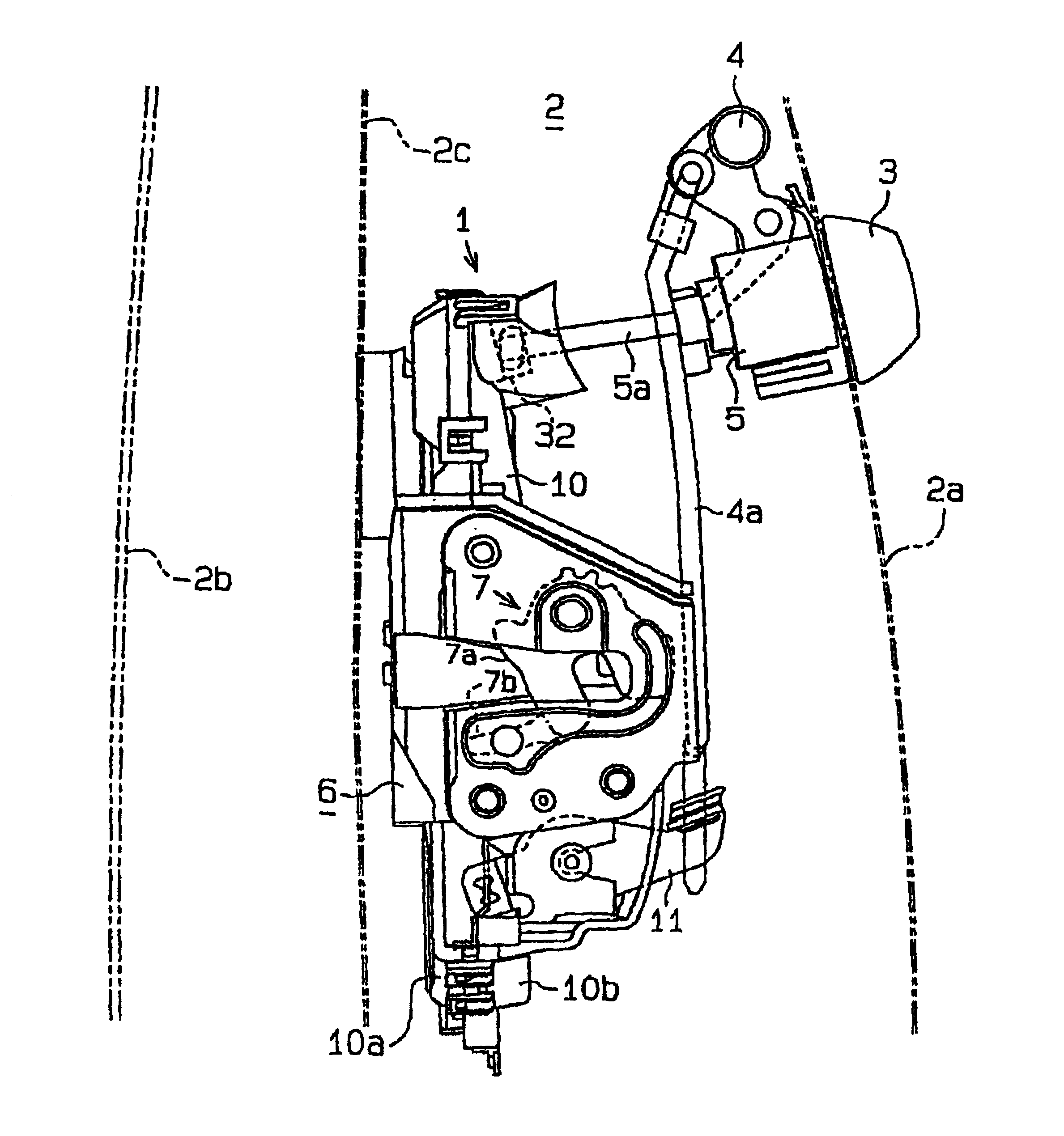
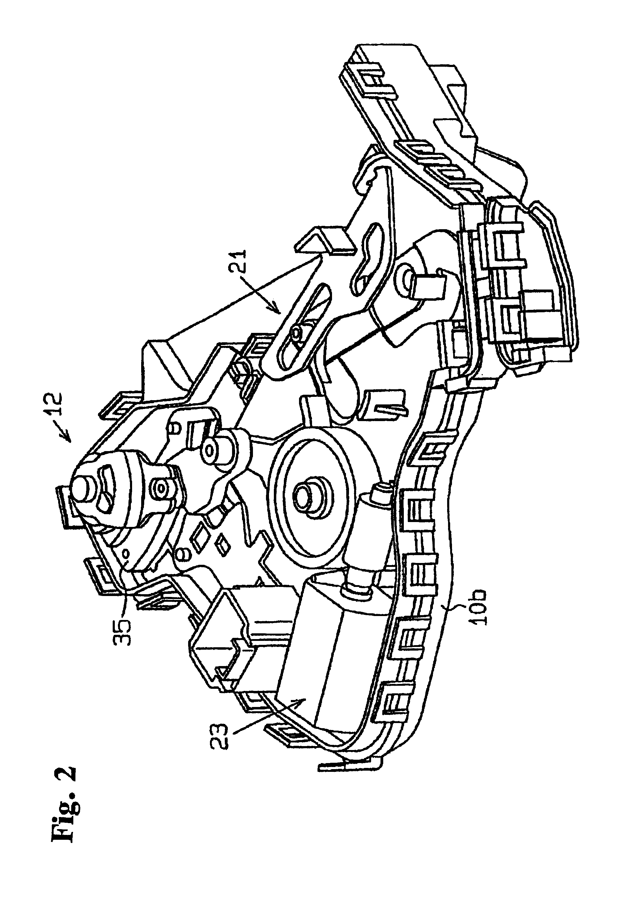
[0028]An embodiment of a vehicle door lock apparatus in accordance with the present invention is described below with reference to FIGS. 1-8. Referring initially to FIG. 1, which is a side view of the vehicle door lock apparatus 1 viewed from the side of a vehicle door 2, the vehicle door 2 includes a door outer panel 2a forming an exterior design or exterior portion, a door trim 2b forming an interior design or interior portion, and a door inner panel 2c disposed between the door outer panel 2a and the door trim 2b. The door outer panel 2a is provided with an outside door handle 3 disposed at an inclined position in accordance with the design or contour of the door outer panel 2a for opening and closing the vehicle door 2.

[0029]The outside door handle 3 is connected to a handle-side link mechanism 4. By pulling out the outside door handle 3, a rod 4a provided at or connected to the handle-side link mechanism 4 is depressed. The outside door handle 3 also accommodates a key cylinder...


PUM


Abstract

A vehicle door lock apparatus includes a lever mechanism directly connected with a key cylinder provided at the outside door handle for locking and unlocking the vehicle door in response to rotation operation of the key cylinder. The lever mechanism is provided with a key rotor directly connected with the key cylinder, and a key lever directly connected with the key rotor. An input shaft of the lever mechanism formed by the key rotor is inclinable relative to an output shaft of the lever mechanism formed by the key lever, and this inclination is absorbed through the connection between the key rotor and the key lever.

Description

[0001]This application is based on and claims priority under 35 U.S.C. §119 with respect to Japanese Application 2000-326809 filed on Oct. 26, 2000, the entire content of which is incorporated herein by reference.FIELD OF THE INVENTION[0002]This invention generally relates to a door lock. More particularly, the present invention pertains to a vehicle door lock apparatus.BACKGROUND OF THE INVENTION[0003]A known vehicle door lock apparatus is disclosed in a Japanese patent application publication published on Jun. 13, 2000 as Toku-Kai 2000-160900. The disclosed vehicle door lock apparatus includes a link mechanism connected with an outside handle and an inside handle for allowing vehicle door opening, a lever mechanism directly connected with a key cylinder provided at the outside handle for locking and unlocking the vehicle door by conducting a changeover of engagement and disengagement of the link mechanism in response to rotation operation of the key cylinder, and a drive mechanism...

Claims


Application Information

Patent Timeline
Patent Type & Authority Patents(United States)
IPC IPC(8): E05B17/00E05B17/04E05B65/12E05B65/20B60J5/00B60R25/01E05B83/36E05B85/06
CPCE05B17/041E05B85/02E05B85/06E05B83/36Y10T70/5889Y10T70/7706Y10T70/8838
Inventor FUKUNAGA, KATSUTOSHISUZUMURA, MAKOTOAKIZUKI, RYUJIROKONOMOTO, NORIOMURAMATSU, AKIRAHAYAKAWA, SHIGERUSONO, YASUHIKO
Owner AISIN SEIKI KK
Why Eureka
Try Eureka