Heat dissipation device

a heat dissipation device and heat dissipation technology, which is applied in the direction of tubular elements, cooling/ventilation/heating modifications, and modifications by conduction heat transfer, etc., can solve the problems of poor heat dissipation efficiency, the heat dissipation effect provided by this type of heat dissipation method is rather limited, and the hardware is not high performan

Active Publication Date: 2022-01-20
AURAS TECH
View PDF10 Cites 1 Cited by
  • Summary
  • Abstract
  • Description
  • Claims
  • Application Information

AI Technical Summary

Benefits of technology

The heat dissipation device described in this patent has holes in the first fin set that are bigger than the cross-sectional area of the heat pipes they contain. These holes are designed to sleeve the heat pipes, which helps to improve the heat transfer process. This design allows for better cooling of the device, which can help to increase its efficiency and lifespan.

Problems solved by technology

In the face of modernization, computers and various other electronic devices have seen rapid developments and continuously improved performance However, along with these improvements, heat dissipation has become one of the major issues faced by high performance hardware today.
However, heat dissipation effect provided by this type of heat dissipation method is rather limited.
However, when faced with the high heat generated by high power processors, heat cannot be dissipated effectively, resulting in poor heat dissipation efficiency.

Method used


Image

  • Heat dissipation device
  • Heat dissipation device
  • Heat dissipation device

Examples


Embodiment Construction

[0024]Embodiments of the present disclosure are illustrated with specific implementations. Other advantages and technical effects of the present disclosure can be readily understood by one with ordinary skills in the art upon reading the disclosure provided herein, and can be used or applied in other different implementations.

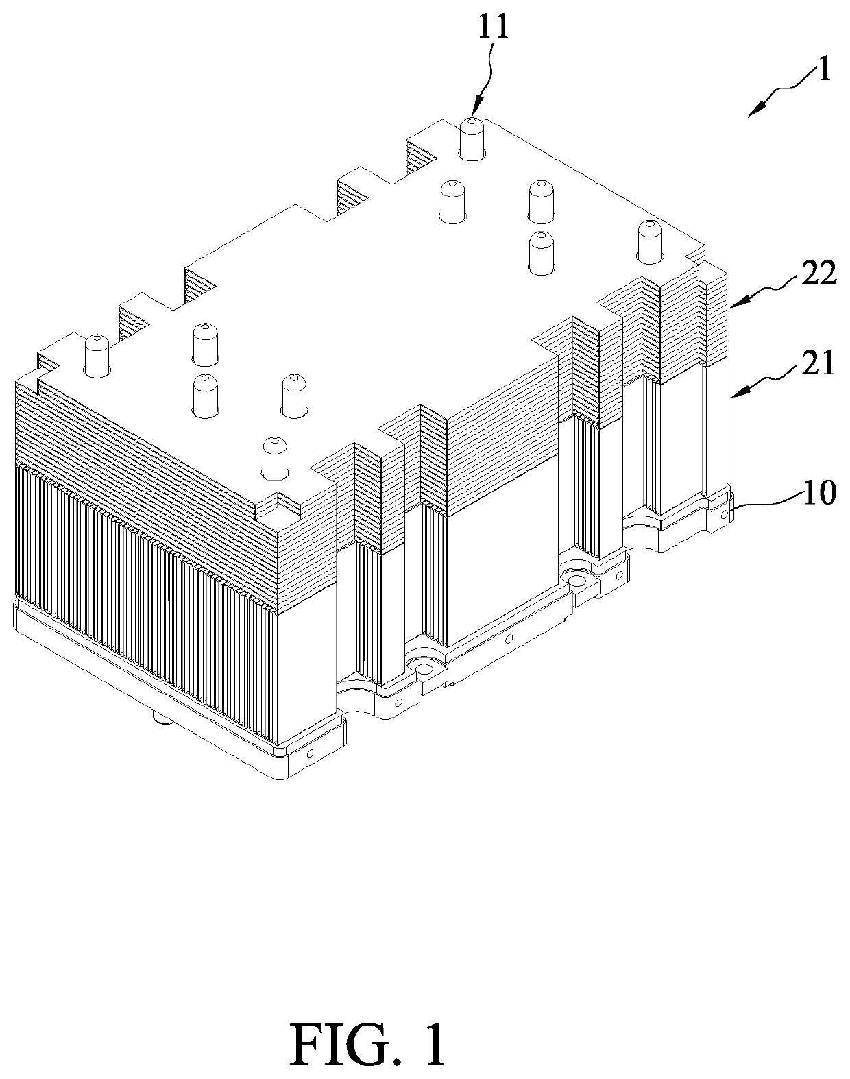
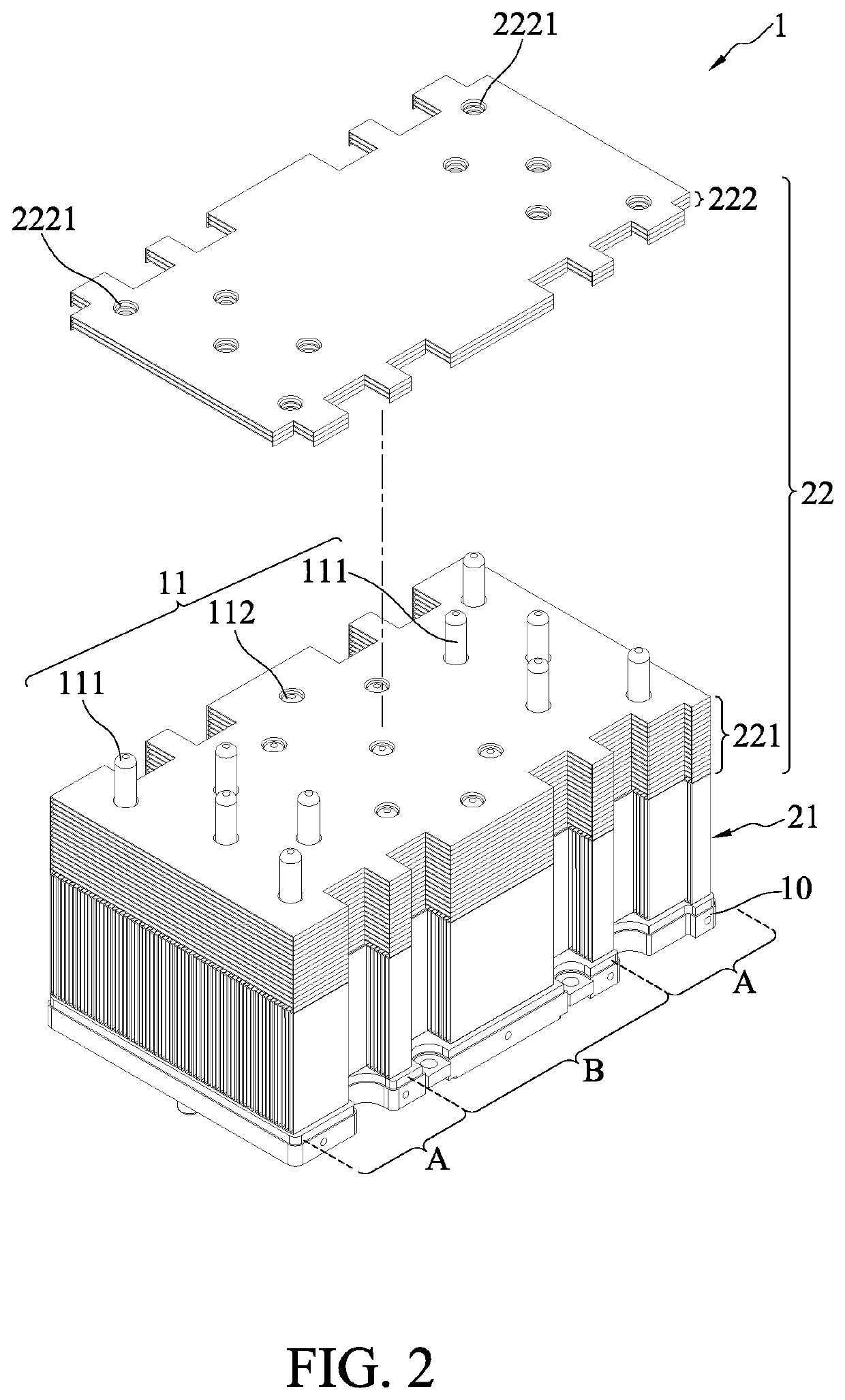
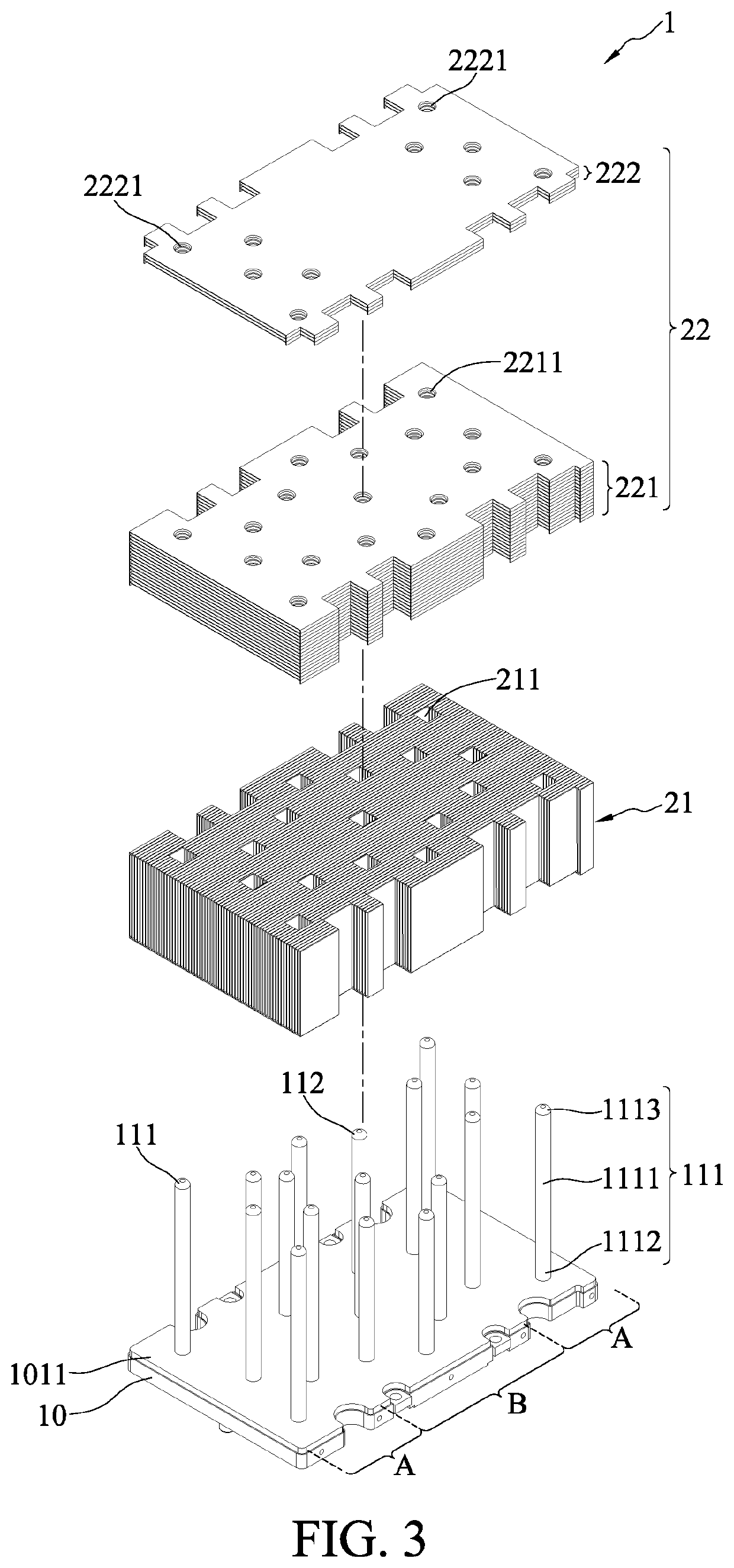
[0025]Referring to FIGS. 1, 2 and 3, a heat dissipation device 1 in accordance with the present disclosure includes a vapor chamber unit 10, a heat pipe set 11, a first fin set 21 and a second fin set 22. The heat pipe set 11 is provided on an outer surface 1011 of the vapor chamber unit10. The first fin set 21 is provided on the outer surface 1011 of the vapor chamber unit 10 and sleeved the heat pipe set 11 and partially exposing the heat pipe set 11. The second fin set 22 is stacked on the first fin set 21 and sleeved the heat pipe set 11 exposed by the first fin set 21 and partially exposing the heat pipe set 11. In an embodiment, the overall form factors o...


PUM


Abstract

A heat dissipation device is provided and includes a vapor chamber unit, a heat pipe set provided on an outer surface of the vapor chamber unit, a first fin set provided on the outer surface of the vapor chamber unit and sleeving the heat pipe set, and a second fin set stacked on the first fin set and sleeving the heat pipe set, where the fin arrangement direction of the first fin set is different from the fin arrangement direction of the second fin set.

Description

BACKGROUND1. Technical Field[0001]The present disclosure relates to the heat dissipation field, and more specifically, to a heat dissipation device with a vapor chamber and fin sets.2. Description of Related Art[0002]In the face of modernization, computers and various other electronic devices have seen rapid developments and continuously improved performance However, along with these improvements, heat dissipation has become one of the major issues faced by high performance hardware today. In general, computers and electronic devices employ heat dissipation components for dissipating the heat away. For example, a thermal paste or cooling fins can be attached onto an electronic component that is subjected to heat dissipation in order to absorb and disperse heat generated by the electronic component. However, heat dissipation effect provided by this type of heat dissipation method is rather limited. Heat dissipation components that use phase changes of working fluids for heat transfer...

Claims


Application Information

Patent Timeline
Patent Type & Authority Applications(United States)
IPC IPC(8): F28D15/04F28D15/02F28F1/32F28F1/22
CPCF28D15/046F28D15/0275F28D15/0283F28F1/22F28F1/325H05K7/2039H05K7/20336H05K7/20327H05K7/20309F28D15/04F28F1/32F28D15/0233H05K7/202
Inventor CHEN, CHIH-WEICHANG, CHENG-JUHUANG, JYUN-WEI
Owner AURAS TECH
Why Eureka
Try Eureka