Wavelength Conversion Element and Method for Manufacturing Same
a technology of wavelength conversion and manufacturing method, which is applied in the direction of optical elements, optical waveguide light guides, instruments, etc., can solve the problems of difficult to obtain the desired waveguide structure, difficult to fabricate a nonlinear optical waveguide having desired nonlinear optical characteristics as designed, and difficult to form an ln structure sized or shaped as designed, etc., to achieve efficient fabrication
- Summary
- Abstract
- Description
- Claims
- Application Information
AI Technical Summary
Benefits of technology
Problems solved by technology
Method used
Image
Examples
first embodiment
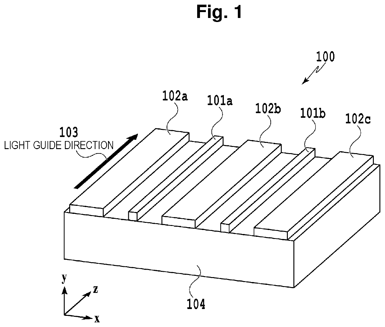
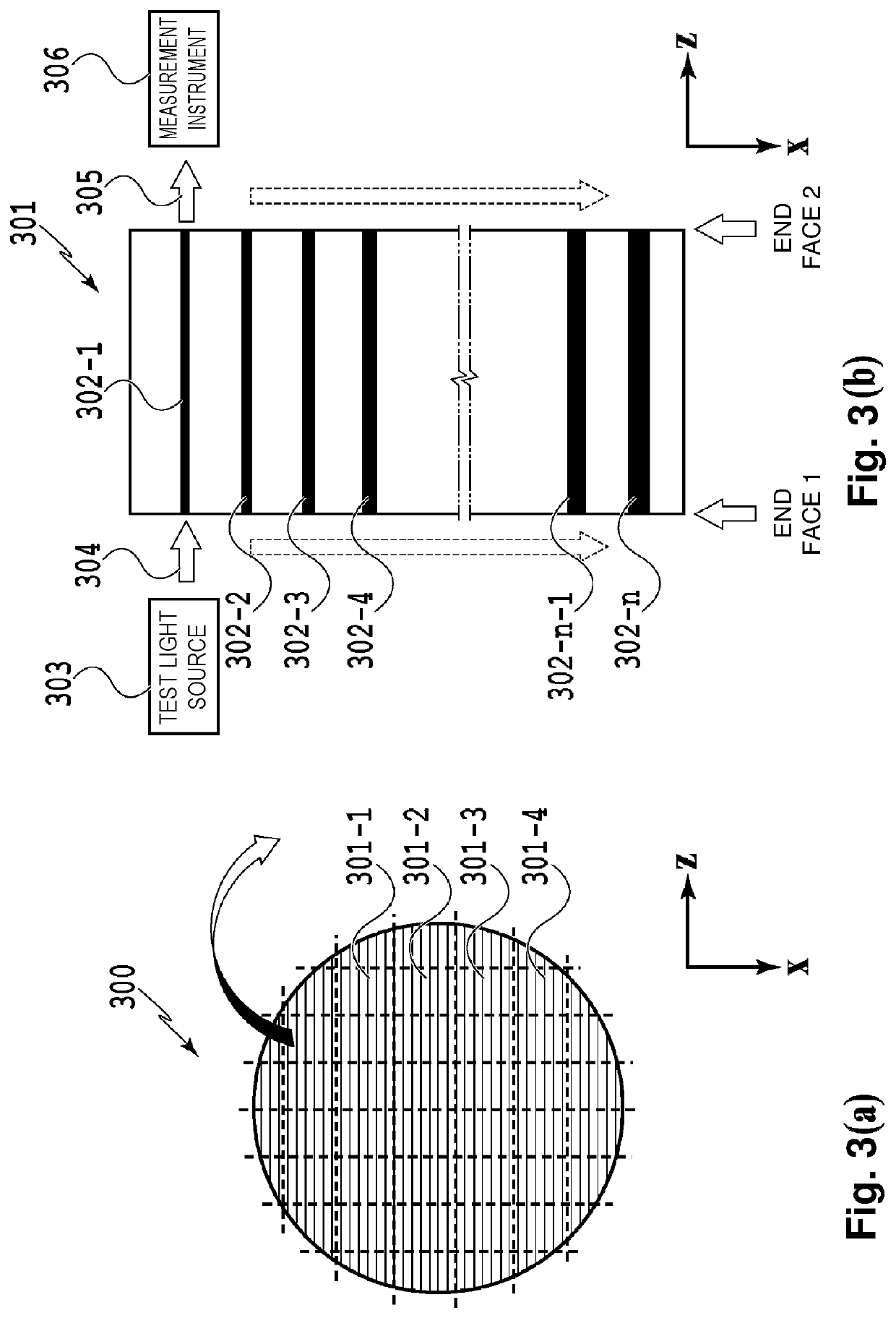
[0043]FIG. 4 is a conceptual diagram for illustrating a configuration of a wavelength conversion device according to a first embodiment of the present invention. The configuration of the wavelength conversion device according to the present invention corresponds to the configuration of the conventional wavelength conversion device chip 100 shown in FIG. 1. A wavelength conversion device 400 in FIG. 4 is a chip including a plurality of waveguides cut from a substrate (wafer) in which a large number of waveguides (arrayed waveguides) is formed. The wavelength conversion device 400 includes a plurality of waveguides 401a and 401b and slab waveguides 402a to 402c that are formed substantially in parallel with and spaced apart from the plurality of waveguides. All the waveguides are formed along a z-axis direction, and light can be input to and output from the wavelength conversion device 400 at two chip end faces (x-y faces) that are perpendicular to the waveguides (z-axis) and oriented...
second embodiment
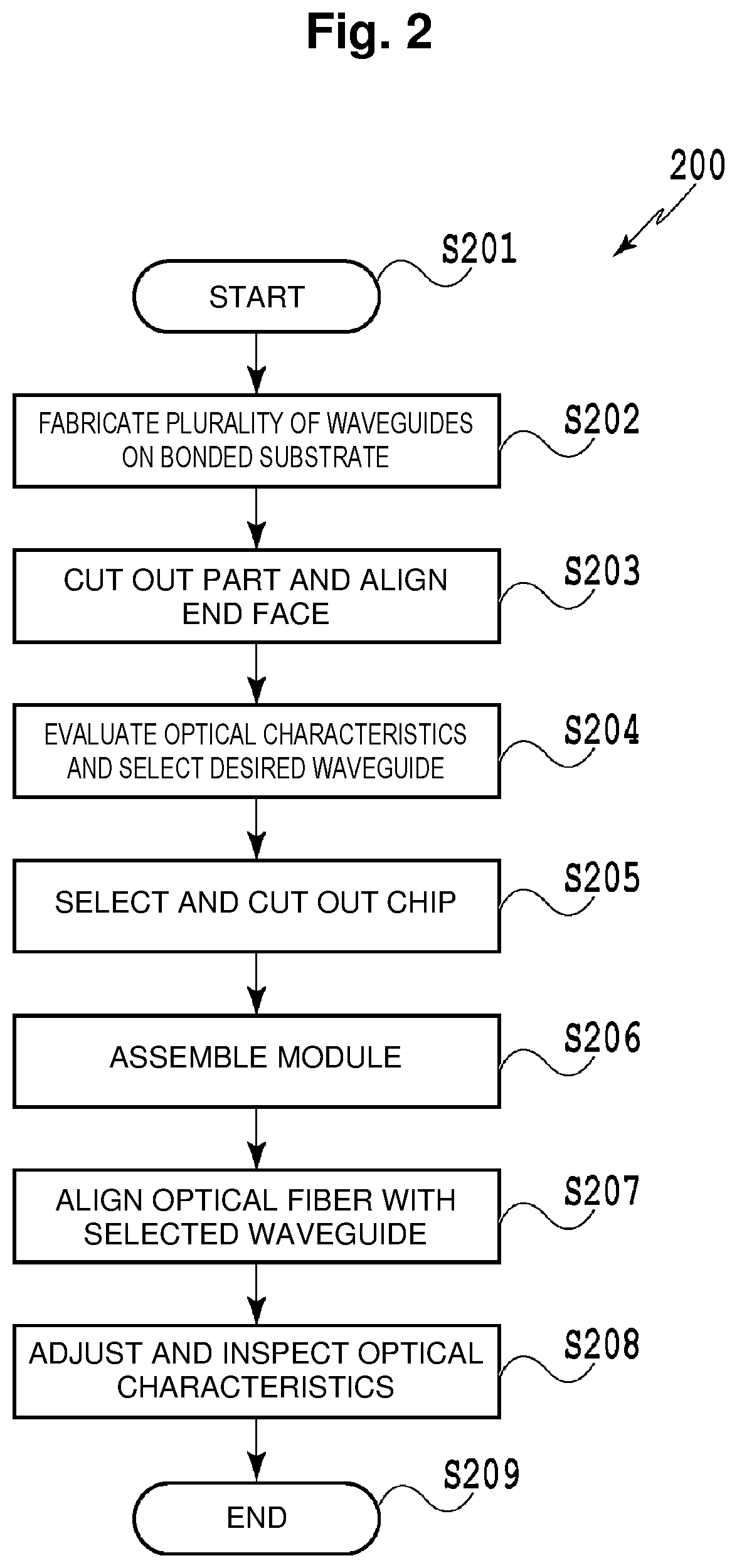
[0055]In steps for fabricating the wavelength conversion device, arrayed waveguide having cores reduced in size to increase the wavelength conversion efficiency are fabricated. At this point, slab waveguides, which are intrinsically unwanted, are formed as a result of the problems of the dry etching being solved. With the wavelength conversion device according to the first embodiment, in order to efficiently perform the step of selecting a waveguide having desired characteristics from a plurality of waveguides, the slab waveguides have a grating structure. With regard to a second embodiment, a configuration of a wavelength conversion device that allows steps (Steps 206 to 208 in FIG. 2) of mounting the wavelength conversion device in a module after selecting a desired waveguide and then performing an adjustment and an inspection of the wavelength conversion device to be more efficiently performed will be described. In addition, a method for fabricating the wavelength conversion devi...
example 1
[0069]Referring to FIG. 5 again, in an example of the wavelength conversion device 500 according to the first embodiment, the nonlinear waveguides 501-1 to 501-n for wavelength conversion are made of a ferroelectric primarily made up of lithium niobate whose spontaneous polarization is periodically inverted. A lower substrate constituting a cladding portion is made of lithium tantalite having a coefficient of thermal expansion close to that of lithium niobate. The material forming the waveguides 501-1 to 501-n is a nonlinear optical material. The material forming the substrate constituting the cladding or an over-cladding may be any material that is transparent to the light in the two wavelength bands used for wavelength conversion, such as a dielectric material or semiconductor material, such as silicon, silicon dioxide, lithium niobate, indium phosphide, or polymers, or a compound of such a dielectric material or semiconductor material and an additive. The two wavelength bands can...
PUM
 Abstract
Description
Claims
Application Information
 - R&D
- Intellectual Property
- Life Sciences
- Materials
- Tech Scout
- Unparalleled Data Quality
- Higher Quality Content
- 60% Fewer Hallucinations
Browse by: Latest US Patents, China's latest patents, Technical Efficacy Thesaurus, Application Domain, Technology Topic, Popular Technical Reports.
© 2025 PatSnap. All rights reserved.Legal|Privacy policy|Modern Slavery Act Transparency Statement|Sitemap|About US| Contact US: help@patsnap.com


