Suspension thrust bearing device with dust boot retainer

a thrust bearing and retainer technology, applied in the direction of shock absorbers, elastic bearings, transportation and packaging, etc., can solve the problem that the thrust bearing device has the major drawback of requiring a large number of operations

Pending Publication Date: 2022-01-27
AB SKF
View PDF11 Cites 0 Cited by
  • Summary
  • Abstract
  • Description
  • Claims
  • Application Information

AI Technical Summary

Benefits of technology

[0017]The retaining hook(s) lead to a better bonding feature between the flexible material of the vibration damping seat and the rigid material of the main body. As a matter of fact, with such retaining hook(s), the axial length of the axial portion is increased thus leading to more contact surface between the main body and this axial portion.
[0023]In another embodiment, the retaining hook may extend inwards. In this case, the retaining hook may project inwards with regard to the bore of the axial portion of the main body of the lower support cap. The retaining hook may comprise a radial heel recovering the free end of the axial portion of the main body of the lower support cap. The bonding between the vibration damping seat and the main body is further increased.

Problems solved by technology

Such suspension thrust bearing device has the major drawback to require a large number of operations to be mounted around the damping piston rod.

Method used


Image

  • Suspension thrust bearing device with dust boot retainer
  • Suspension thrust bearing device with dust boot retainer
  • Suspension thrust bearing device with dust boot retainer

Examples


Embodiment Construction

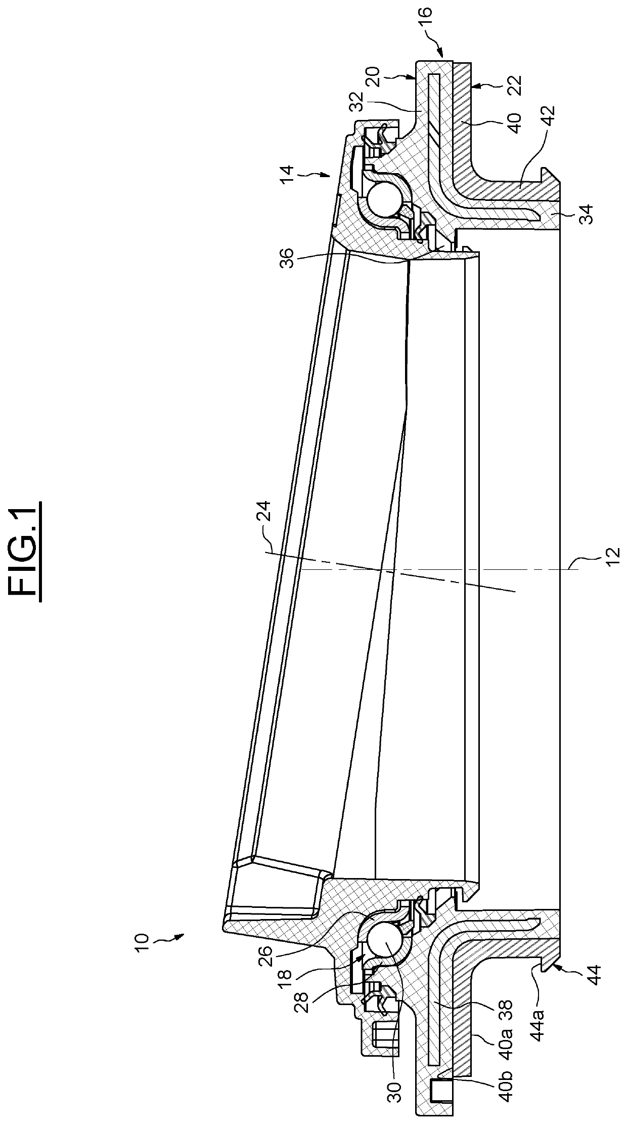
[0030]The suspension thrust bearing device 10 represented on FIG. 1 is adapted to be installed between a top retainer seat suitable of resting, directly or indirectly, in an element of a chassis of the motor vehicle, and a suspension spring.

[0031]The device 10, with an axis 12, comprises an upper bearing cap 14, a lower support cap 16, and a rolling bearing 18 axially interposed between the caps 14, 16. In the illustrated example, the caps 14, 16 are mounted in direct contact with the rolling bearing 18 without the interposition of an intermediate element. Alternatively, the caps 14, 16 may be mounted in indirect contact with the rolling bearing 18 with interposition of an intermediate element.

[0032]As will be described later, the lower support cap 16 comprises a rigid main body 20 in contact with the rolling bearing 18, and a flexible insulator or vibration damping seat 22 secured to the main body. The vibration damping seat 22 delimits a bearing surface for the suspension spring a...


PUM


Abstract

A suspension thrust bearing device provides a lower support cap, an upper bearing cap and at least one bearing arranged between the caps. The lower support cap includes a rigid main body in contact with the bearing, and a flexible vibration damping seat delimiting a bearing surface for the upper end of a suspension ring. The vibration damping seat of the lower support cap is secured to the main body and is provided with at least one retaining hook extending at least in the radial direction and axially offset with respect to the bearing surface on the side opposite to the bearing.

Description

CROSS-REFERENCE TO RELATED APPLICATIONS[0001]This application claims priority to South Korea Patent Application no. 10-2020-0090180, filed Jul. 21, 2020, the contents of which is fully incorporated herein by reference.TECHNICAL FIELD OF THE INVENTION[0002]The present invention relates to the field of suspension thrust bearing devices, used in particular for motor vehicles in the suspension struts of the steered road wheels.BACKGROUND OF THE INVENTION[0003]A suspension thrust bearing device is generally provided with a rolling bearing comprising an upper ring and a lower ring between which are positioned rolling elements, for example balls or rollers, and with lower and upper caps. The lower and upper caps form housings for the rings of the rolling bearing and provide the interface between the rings and the neighboring elements.[0004]The suspension thrust bearing device is arranged in the top part of the suspension strut between the vehicle body and a suspension spring. The suspensio...

Claims


Application Information

Patent Timeline
Patent Type & Authority Applications(United States)
IPC IPC(8): B60G15/06F16C19/10F16C33/76
CPCB60G15/068F16C19/10B60G2204/128B60G2204/418F16C2326/05F16C33/761F16C27/08F16F9/38B60G15/063
Inventor MONTBOEUF, BRUNORENAUDON, JORDAN
Owner AB SKF
Why Eureka
Try Eureka