
Automatic light blocking device for vehicle

Pending Publication Date: 2022-01-27
GEUM YOUNG SUNG
View PDF0 Cites 1 Cited by
  • Summary
  • Abstract
  • Description
  • Claims
  • Application Information

AI Technical Summary

Benefits of technology

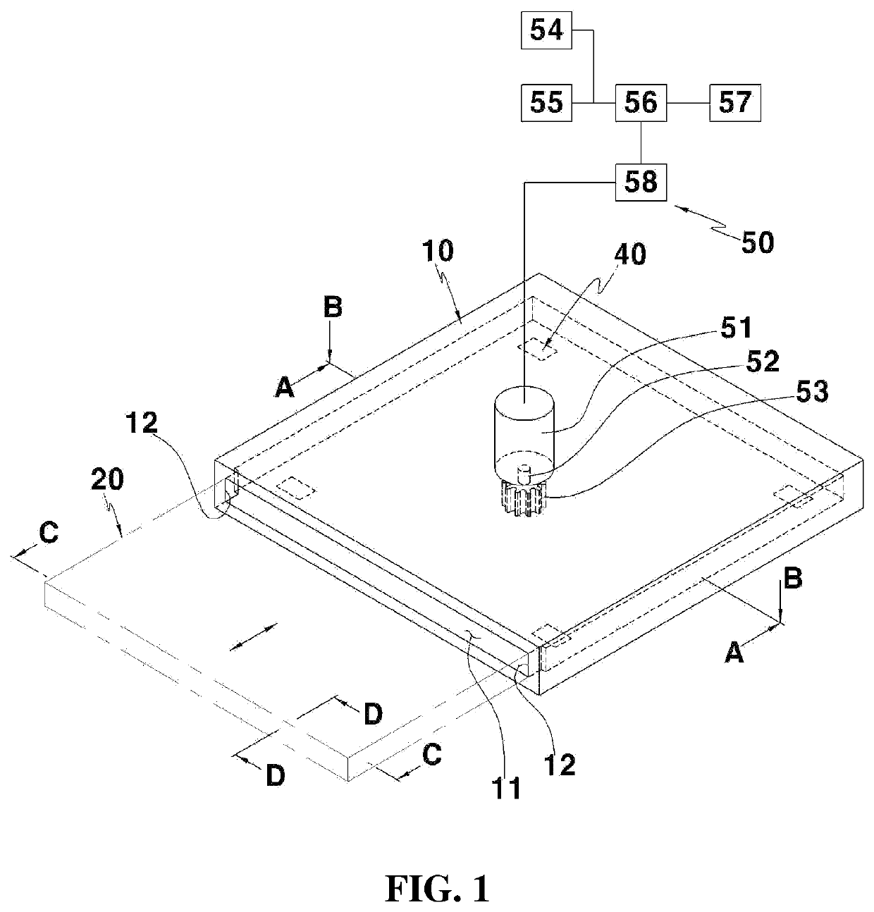
The present invention is about an automatic light blocking device for vehicles. The device has a light blocking slider that can be slid out from the roof or ceiling of a vehicle to block sunlight from coming in. There can be multiple sliders to block sunlight from different directions. The device also has a light blocking body that is installed on the roof or ceiling to prevent sunlight from being emitted and to prevent excessive heat from getting into the vehicle. The slider can be locked in place to prevent it from moving or getting separated. The device can be easily attached and detached from the roof or ceiling of the vehicle. The slider can also be automatically slid out through a driving unit to prevent accidents. Overall, the invention provides a simple yet effective way to block sunlight in a vehicle to improve safety and comfort.

Problems solved by technology

However, the existing art simply limits application of an LCD and does not present a method of concretely and effectively applying an LCD in terms of user convenience or safety.

Method used


Image

  • Automatic light blocking device for vehicle
  • Automatic light blocking device for vehicle
  • Automatic light blocking device for vehicle

Examples


first embodiment

[0035]FIG. 1 is a perspective view illustrating an automatic light blocking device for vehicle according to the present disclosure.

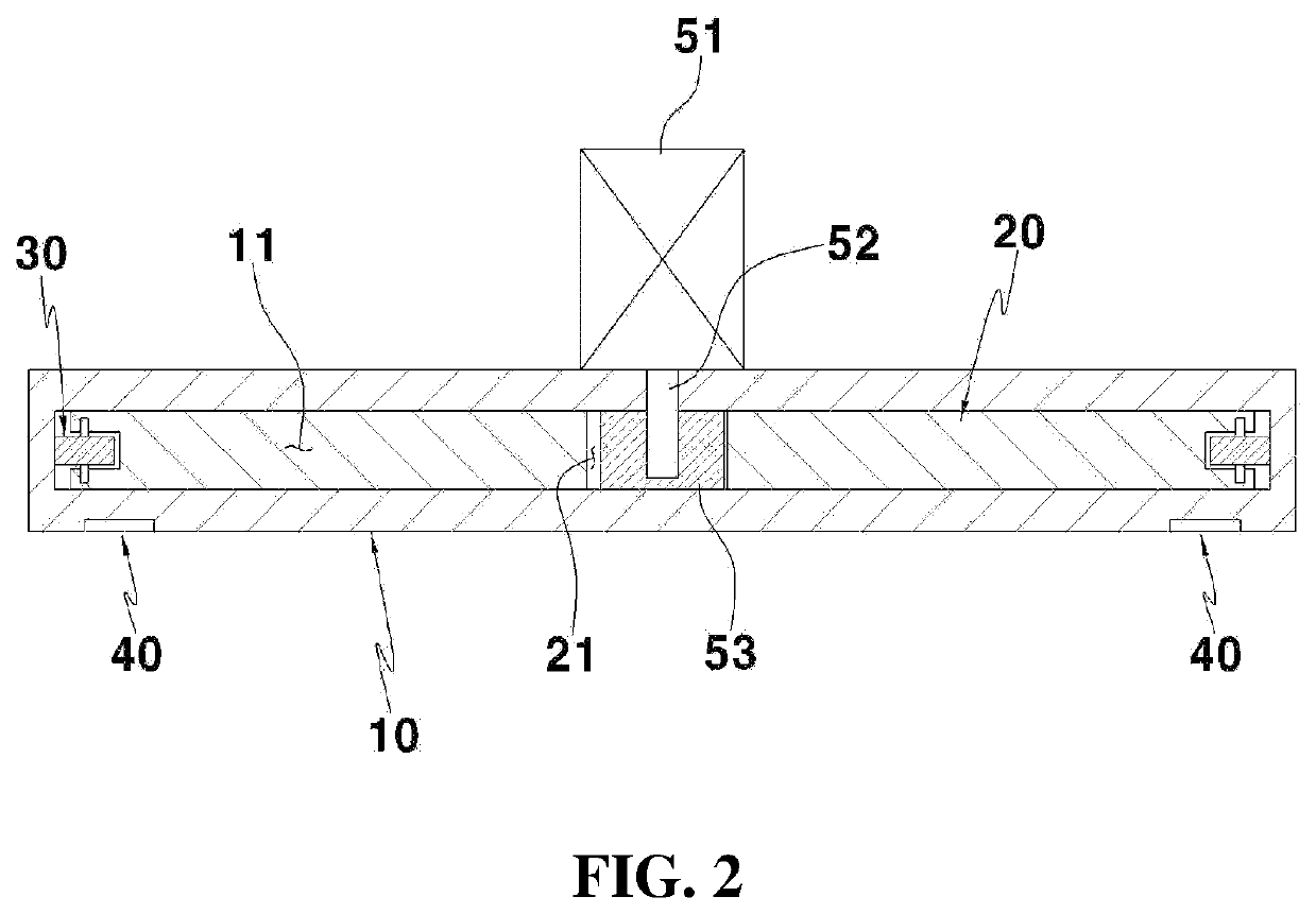
[0036]FIG. 2 is a longitudinal sectional view cut along a line A-A of FIG. 1.

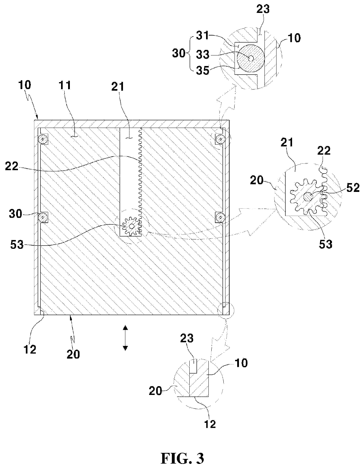
[0037]FIG. 3 is a cross-sectional view cut along a line B-B of FIG. 1.

[0038]FIG. 4 is a front view illustrating a detachable unit in the automatic light blocking device for vehicle according to the first embodiment of the present disclosure.

[0039]FIG. 5 illustrates an operation state of the detachable unit in the automatic light blocking device for vehicle according to the first embodiment of the present disclosure.

[0040]FIG. 6 is a longitudinal sectional view cut along a line C-C of FIG. 1.

[0041]FIG. 7 is a longitudinal sectional view cut along a line D-D of FIG. 1.

[0042]FIG. 8 is a perspective view illustrating a first modification example of the automatic light blocking device according to the first embodiment of the present disclosure.

[0043]FIG. 9 is a longitudinal sectional...

second embodiment

[0055]FIG. 21 is a perspective view illustrating an automatic light blocking device for vehicle according to the present disclosure.

[0056]FIG. 22 is a longitudinal sectional view cut along a line C-C of FIG. 21.

[0057]FIG. 23 is a longitudinal sectional view cut along a line D-D of FIG. 21.

third embodiment

[0058]FIG. 24 is a perspective view illustrating an automatic light blocking device for vehicle according to the present disclosure.

[0059]FIG. 25 is a longitudinal sectional view illustrating the automatic light blocking device for vehicle according to the third embodiment of the present disclosure.

[0060]FIG. 26 is a plan sectional view of a light emitting housing schematically illustrating a coupling state of an opening and closing door as an internal configuration of the light emitting housing in the automatic light blocking device for vehicle according to the third embodiment of the present disclosure.

[0061]FIG. 27 is a plan sectional view illustrating a modification example of a light blocking slider in the automatic light blocking device for vehicle according to the third embodiment of the present disclosure.


PUM


Abstract

Provided is an automatic light blocking device for a vehicle, wherein a light blocking slider protrudes in a sliding manner from the ceiling or roof of the vehicle in order to block sunlight shining into the interior of the vehicle. To this end, an automatic light blocking device for a vehicle comprises: a light blocking body provided on the ceiling or roof of the vehicle and having at least one sliding groove which is open in the direction in which light is to be blocked; a light blocking slider which is slidably inserted into and coupled to the sliding groove; and a driving unit for sliding the light blocking slider along the light blocking body by using power applied from the vehicle.

Description

TECHNICAL FIELD[0001]The present disclosure relates to an automatic light blocking device for vehicle, and more particularly, to an automatic light blocking device for vehicle in which a light blocking slider protrudes in a sliding manner from a ceiling or roof of a vehicle and blocks sunlight from being emitted to an interior of the vehicle.RELATED ART[0002]In general, vehicle glass passes strong sunlight as is and all passengers including a driver are exposed to ultraviolet rays. In particular, in summer, an air conditioner is turned on strongly due to hot sunlight in the middle of the day. Alternatively, depending on cases, cellophane paper for blocking sunlight is attached to the glass.[0003]To solve this, a light blocking method in a form of attaching a liquid crystal display (LCD) to the front window of a vehicle is proposed. However, the existing art simply limits application of an LCD and does not present a method of concretely and effectively applying an LCD in terms of use...

Claims


Application Information

Patent Timeline
IPC IPC(8): B60J7/057B60Q3/53B60J7/00B60R11/00
CPCB60J7/0573B60Q3/53B60R2011/0028B60R11/00B60R2011/0057B60J7/0038B60Q3/208B60Q3/74B60J1/2011B60J7/02F16H19/04B60Q3/51B60J7/003
Inventor GEUM, YOUNG SUNGKEUM, TAE HO
Owner GEUM YOUNG SUNG
Learn More