
Electrification apparatus for electric dust collection

Pending Publication Date: 2022-02-03
LG ELECTRONICS INC
View PDF0 Cites 0 Cited by
  • Summary
  • Abstract
  • Description
  • Claims
  • Application Information

AI Technical Summary

Benefits of technology

This patent text describes an electrification apparatus for electric dust collection that maximizes space efficiency and reduces manufacturing costs. The apparatus includes an electrification module with a high voltage supplier integrated into a cover module, eliminating the need for an additional installation frame. A single high voltage cable is used to connect the high voltage supplier to the discharge tip, simplifying the wire structure and reducing manufacturing costs. A connector is also included for external power supply, improving cleaning and maintenance convenience. Overall, this electrification apparatus for electric dust collection offers improved performance and efficiency while reducing manufacturing costs.

Problems solved by technology

An air conditioner for vehicle having severe space constraints may limit the provision of the space to accommodate the high voltage supplier.
Therefore, the electrification apparatus may have a complicated structure.

Method used


Image

  • Electrification apparatus for electric dust collection
  • Electrification apparatus for electric dust collection
  • Electrification apparatus for electric dust collection

Examples


first embodiment

[0176]A configuration in which the tip holder 1500 is separately manufactured is described with reference to FIGS. 8 to 11.

[0177]The tip holder 1500 includes a hexahedral main body 1510 to support the discharge tip 1100 and the high voltage cable 1600, and the main body 1510 includes a first half body 1511 and a second half body 1512. The first half body 1511 and the second half body 1512 may be manufactured separately from the discharge tip 1100 and the high voltage cable 1600 by injection molding.

[0178]The discharge tip 1100 and the high voltage cable 1600 are pressed and supported by the first half body 1511 and the second half body 1512 in a state in which the discharge tip 1100 and the high voltage cable 1600 are at least partially disposed between the first half body 1511 and the second half body 1512.

[0179]The first half body 1511 includes a cable seating groove 1511b to accommodate the high voltage cable 1600 and the discharge tip 1100 and having a shape corresponding to ou...

second embodiment

[0191]Referring to FIG. 12, a tip holder 1500 and a discharge tip 1100 manufactured by insert injection are described.

[0192]As shown in FIG. 12, one end of a discharge brush 1110 in the form of a carbon brush is connected to one end of a core wire 1601 of a high voltage cable 1600 through a terminal 1120. One end of the core wire 1601 of the high voltage cable 1600 is exposed to the outside with a cable sheath 1602 peeled off.

[0193]When one end of the discharge brush 1110 contacts one end of the core wire 1601 of the high voltage cable 1600, the terminal 1120 covers a contact point in a circumferential direction and presses the contact point thereof.

[0194]The discharge brush 1110 of the discharge tip 1100 may be electrically connected to the cable 1600 through the terminal 1120.

[0195]A heat shrinkable tube 1130 surrounds at least the contact point between the discharge brush 1110 and the terminal 1120 as shown in FIG. 12. In this case, the heat shrinkable tube 1130 may extend to th...


PUM


Abstract

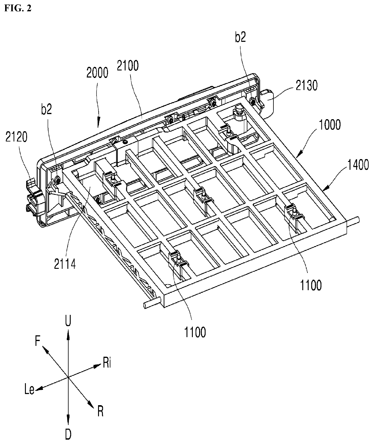
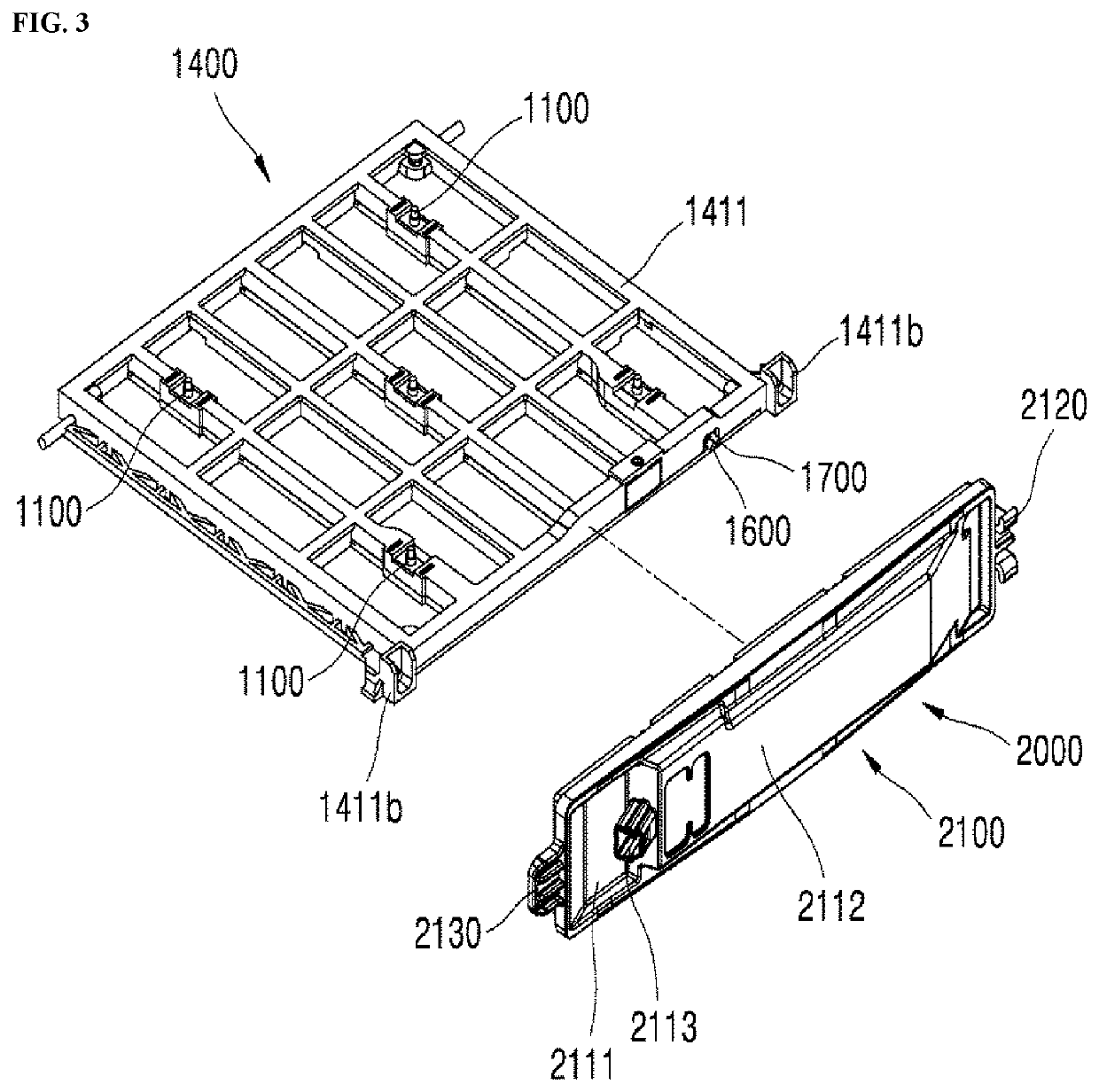
An electrification apparatus for dust collection includes an electrification module configured to generate an ion that is emitted to air. The electrification module includes: at least one discharge tip configured to emit the ion in a direction opposite to a flow direction of the air, a conductive plate configured to generate a potential difference with the discharge tip, a frame that defines an appearance of the electrification module and that supports the discharge tip and the conductive plate, and a high voltage supplier configured to generate a voltage to supply the voltage to the discharge tip.

Description

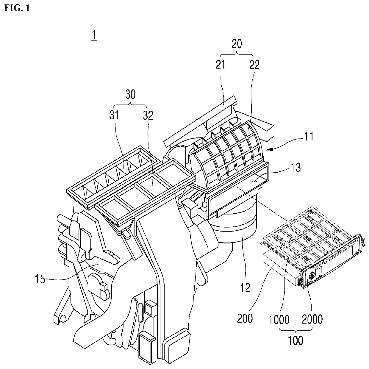
CROSS-REFERENCE TO RELATED APPLICATION[0001]This application claims priority to and the benefit of Korean Patent Application No. 10-2020-0095188, filed on Jul. 30, 2020, No. 10-2020-0131338, filed on Oct. 12, 2020, and No. 10-2021-0014207, filed on Feb. 1, 2021, the disclosure of which is incorporated herein by reference in its entirety.BACKGROUNDTechnical Field[0002]The present disclosure relates to an electrification apparatus for electric dust collection, and one particular implementation relates to an electrification apparatus for electric dust collection including a high voltage supplier configured to generate a voltage to supply the voltage to a discharge tip disposed in a cover module, thereby maximizing space utilization and space efficiency.Description of Related Art[0003]A method of removing particles may include two processes of electrification and dust collection. The method may electrify the dust and collect the electrified dust in a dust collecting filter.[0004]Example...

Claims


Application Information

Patent Timeline
IPC IPC(8): B03C3/47B03C3/41
CPCB03C3/47B60H3/0078B03C3/41B03C2201/30B03C2201/28B03C2201/10B03C2201/08B03C2201/06B03C3/12B03C3/155B03C3/38B03C3/60B03C3/86B60H3/0608
Inventor SHIN, NAMGYULEE, DONG HYUKPARK, NAEHYUNKIM, AH RAMLEE, GISEOP
Owner LG ELECTRONICS INC
Learn More