
Rotor for a wind turbine, and method

a technology for wind turbines and rotors, applied in the field of rotors for wind turbines, can solve the problems of high load at the connecting point between the rotor blade and the hub, damage to the wind turbine itself, and considerable further damage in the surrounding area of the wind turbine, so as to reduce or eliminate one or more, simplify the mounting of the rotor, and increase the effect of resource efficiency

Pending Publication Date: 2022-02-03
WOBBEN PROPERTIES GMBH
View PDF8 Cites 2 Cited by
  • Summary
  • Abstract
  • Description
  • Claims
  • Application Information

AI Technical Summary

Benefits of technology

The patent text describes a rotor for a wind turbine that reduces the weight and cost of the rotor while maintaining its strength. The design of the rotor blade-hub connecting point allows for a more compact and cost-effective design. The use of blind holes in the blade-fastening element eliminates the need for wider passage holes, simplifies the mounting process, and improves ergonomics for the installer. The rotor also allows for easier maintenance and simplifies the connection of the rotor blade to the longitudinal bolt. Overall, the techniques described in the patent text result in increased resource efficiency and lower costs.

Problems solved by technology

In addition to the static load on account of the inherent weight of the rotor blades, it is known that high loads occur at the connecting point between the rotor blade and the hub during the rotation of the rotor due to centrifugal forces which arise.
Breaking-off of a rotor blade not only leads to damage to the wind turbine itself, but also can cause considerable further damage in the surrounding area of the wind turbine.
The heavy rotors lead to larger forces and / or moments at the wind turbine.
Furthermore, the mounting of a heavy rotor and / or of a heavy nacelle is made more difficult, such that the positioning of the components is more difficult and, possibly, larger cranes are necessary.

Method used


Image

  • Rotor for a wind turbine, and method
  • Rotor for a wind turbine, and method
  • Rotor for a wind turbine, and method

Examples


Embodiment Construction

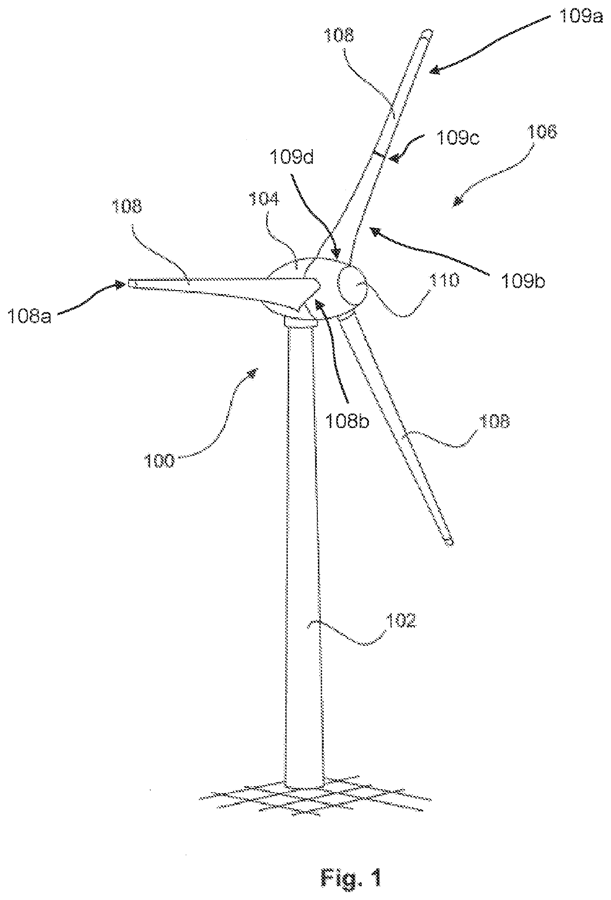
[0067]FIG. 1 shows a schematic three-dimensional view of an exemplary embodiment of a wind turbine. FIG. 1 shows in particular a wind turbine 100 with a tower 102 and with a nacelle 104. A rotor 106 having three rotor blades 108 and having a spinner 110 is arranged on the nacelle 104. During operation, the rotor 106 is set in rotational motion by the wind and in this way drives a generator in the nacelle 104.

[0068]At least one of the rotor blades 108 of the rotor 106 extends from a blade tip 108a to a face side 108b, wherein the rotor blade 108 has a fastening region which is of tubular form and which is arranged adjoining the face side 108b, wherein the fastening region has at its outer circumferential surface and / or at its inner circumferential surface at least one thickened portion, wherein the at least one thickened portion is extended through by a longitudinal bolt cutout, in the form of a passage opening, with two opposite ends, wherein a first end of the longitudinal bolt cut...


PUM


Abstract

A rotor for a wind turbine, to a rotor blade for a wind turbine, to a blade-fastening element for the fastening of a rotor blade, to a wind turbine, and to a method for mounting a rotor. A rotor for a wind turbine, comprising at least one rotor blade which extends from a blade tip to a face side, a hub having a blade-fastening element which, at the rotor-blade side thereof, has a blind hole for receiving a longitudinal bolt for the fastening of a rotor blade to the blade-fastening element, wherein the rotor blade has a fastening region which is of tubular form and which is arranged adjoining the face side, wherein the fastening region has at its outer circumferential surface and / or at its inner circumferential surface at least one thickened portion.

Description

BACKGROUNDTechnical Field[0001]The invention relates to a rotor for a wind turbine, to a rotor blade for a wind turbine, to a blade-fastening element for the fastening of a rotor blade, to a wind turbine, and to a method for mounting a rotor.Description of the Related Art[0002]Wind turbines of the type mentioned in the introduction are well known. Currently, the most common type of wind turbine is the so-called horizontal-axis wind turbine, which is conventionally equipped with three rotor blades, wherein wind turbines having one, two, four or more rotor blades are also possible. Wind turbines have increasingly larger structural forms in order, on the one hand, to be able to achieve a higher rated power and, on the other hand, to allow better utilization of the wind.[0003]Aside from a rotor arranged at a nacelle, wind turbines generally comprise a tower on which the nacelle with the rotor is arranged so as to be rotatable about a substantially vertically oriented axis. Aside from th...

Claims


Application Information

Patent Timeline
Patent Type & Authority Applications(United States)
IPC IPC(8): F03D1/06
CPCF03D1/0658F05B2230/604F05B2260/301F05B2260/30F05B2260/79F03D1/06Y02E10/72
Inventor RUBNER, FLORIANJEPSEN, TORSTEN
Owner WOBBEN PROPERTIES GMBH
Learn More