
Method for automatically calibrating a sensor module and sensor module for detecting material containers in a storage or transport system

Pending Publication Date: 2022-02-03
STEUTE TECH GMBH & CO KG
View PDF0 Cites 0 Cited by
  • Summary
  • Abstract
  • Description
  • Claims
  • Application Information

AI Technical Summary

Benefits of technology

The WO2018 / 087511 A1 describes a sensor unit that uses an absolute direction sensor to measure the position of a rotating element. To account for fluctuating ground, the sensor unit collects a number of measured values and stores them temporarily. However, this method cannot compensate for different installation positions. The sensor unit automatically adjusts its switching angle based on the actual pivot angle range, and includes hysteresis to ensure safe and stable switching. The technical effects of this patent are improved accuracy and reliability of position sensor measurements, regardless of ground fluctuations, and improved hysteresis for safer and non-fluctuating switching.

Problems solved by technology

The disadvantage is that this imposes restrictions with regard to the installation position of the sensor module, since the switching point position of the sensor module relative to its end positions changes with the inclination of the installation position.
In this way, a ground that fluctuates by an average position can be compensated, but the method cannot be used to adapt to different but stationary installation positions.
In addition, high demands are placed on the computing power and storage capacity to be provided in the sensor unit, which necessitates a high outlay.

Method used


Image

  • Method for automatically calibrating a sensor module and sensor module for detecting material containers in a storage or transport system
  • Method for automatically calibrating a sensor module and sensor module for detecting material containers in a storage or transport system
  • Method for automatically calibrating a sensor module and sensor module for detecting material containers in a storage or transport system

Examples


Embodiment Construction

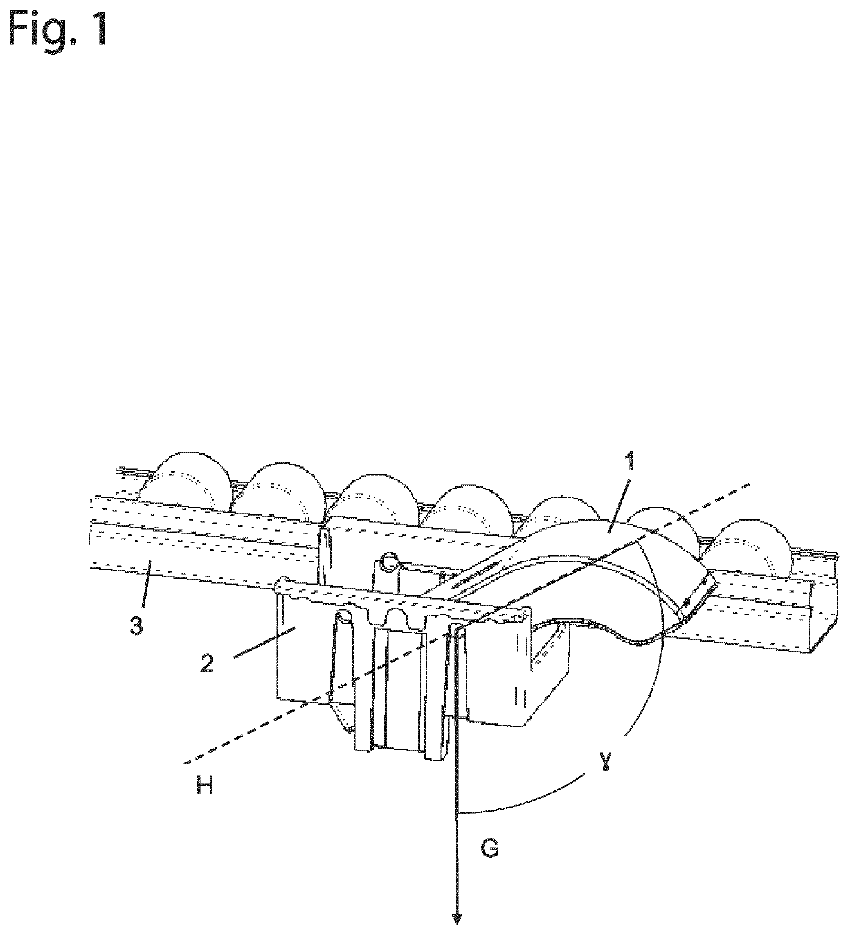
[0018]The exemplary embodiment of a sensor module 1 designed as a rocker shown in FIG. 1 is arranged on an inclined roller conveyor 3 by means of a holder 2. Also shown is the direction G of gravity and an angle γ between a principal plane H of the sensor module 1 and the direction G of gravity, which is indicative of the inclination of the sensor module about its bearing axis in space. The angle γ is the measured quantity of an acceleration or position sensor arranged in the sensor module 1, hereinafter referred to as sensor.

[0019]The weight distribution of the rocker, i.e., of the sensor module 1, is selected so that it assumes a rest position within the holder 2 due to gravity when not depressed. In this rest position, the rocker is shown in FIG. 1.

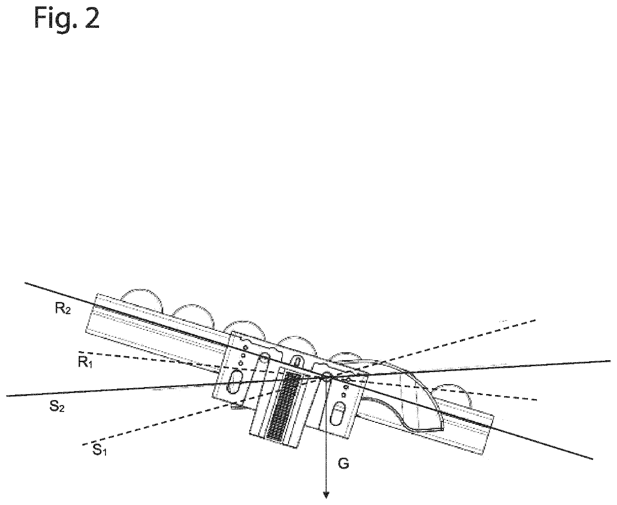
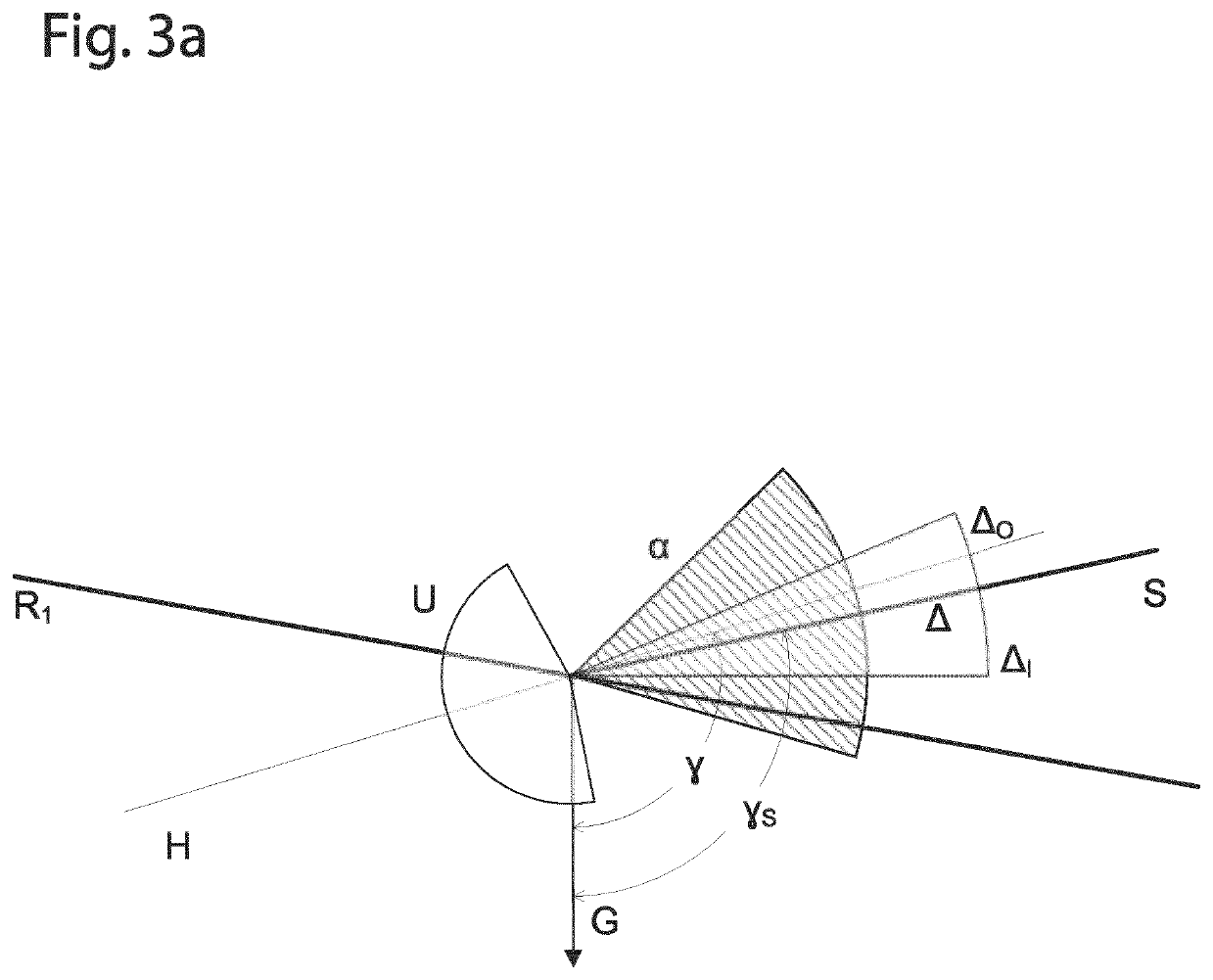
[0020]The position of the sensor module 1 is detected by the sensor in the form of the angle or a measured variable representing the angle, the measured value of which is converted into an output signal in an evaluation unit belonging ...


PUM


Abstract

A method for automatically calibrating a rocker-type sensor module having a position or acceleration sensor involves measuring a position of the sensor module as an angle relative to a fixed spatial direction, and outputting an output signal that depends on whether the measured angle is less than or greater than a switching angle. The output signal is set to a first output value if the measured angle exceeds the switching angle. The switching angle is set to a value corresponding to the measured angle minus an “off” free pivot angle, as long as the value of the measured angle continues to increase. The output signal is set to a second output value if the measured angle falls below the switching angle. The switching angle is set to a value corresponding to the measured angle plus an “on” free pivot angle, as long as the value of the measured angle continues to fall.

Description

BACKGROUND AND SUMMARY OF THE INVENTION[0001]Exemplary embodiments of the invention relate to a method for automatically calibrating a sensor module, which has a position or acceleration sensor, via which a position of the sensor module is measured as an angle relative to a fixed spatial direction, and which emits an output signal which depends on whether the measured angle is greater than or less than a switching angle. Exemplary embodiments of the invention further relate to a sensor module for detecting material containers in a storage or transport system. In particular, exemplary embodiments of the invention relate to such a sensor module that is capable of automatically adapting its characteristics to different installation positions.[0002]DE 20 2017 103 459 U1 discloses a radio sensor module for detecting material containers, the sensor module has a holder and a rocker mounted pivotably therein, wherein a sensor for detecting a position of the rocker and the transmission devic...

Claims


Application Information

Patent Timeline
IPC IPC(8): G01P21/00G01B21/22G01P15/00B65G1/02B65G43/08
CPCG01P21/00G01B21/22B65G43/08B65G1/023G01P15/00G01D18/002G01C9/00B65G13/00
Inventor BÖWERING, GABRIEL
Owner STEUTE TECH GMBH & CO KG
Learn More