Metal Spring Anchor for Advanced Packaging

a technology of advanced packaging and metal springs, applied in the direction of basic electric elements, electrical apparatus, semiconductor/solid-state device details, etc., can solve the problem that the metal spring feature is not easy to break, and achieve the effect of minimizing the total placement error

Active Publication Date: 2022-02-10
LI DONG +1
View PDF10 Cites 0 Cited by
  • Summary
  • Abstract
  • Description
  • Claims
  • Application Information

AI Technical Summary

Benefits of technology

[0008]In this disclosure, a new die placement control methods is invented, which can provide accurate position anchoring during die placement and epoxy molding process. The methods works well with mechanical diced chip, whose dicing errors dominates the position error during FOPLP and FOWLP. Working along w

Problems solved by technology

Firstly, metallic spring feature is not

Method used


Image

  • Metal Spring Anchor for Advanced Packaging
  • Metal Spring Anchor for Advanced Packaging
  • Metal Spring Anchor for Advanced Packaging

Examples


Embodiment Construction

[0038]The following numerous specific detail descriptions are set forth to provide a thorough understanding of various embodiments of the present disclosure. It will be apparent to one skilled in the art, however, that these specific details need not be employed to practice various embodiments of the present disclosure. In other instances, well known components or methods have not been described.

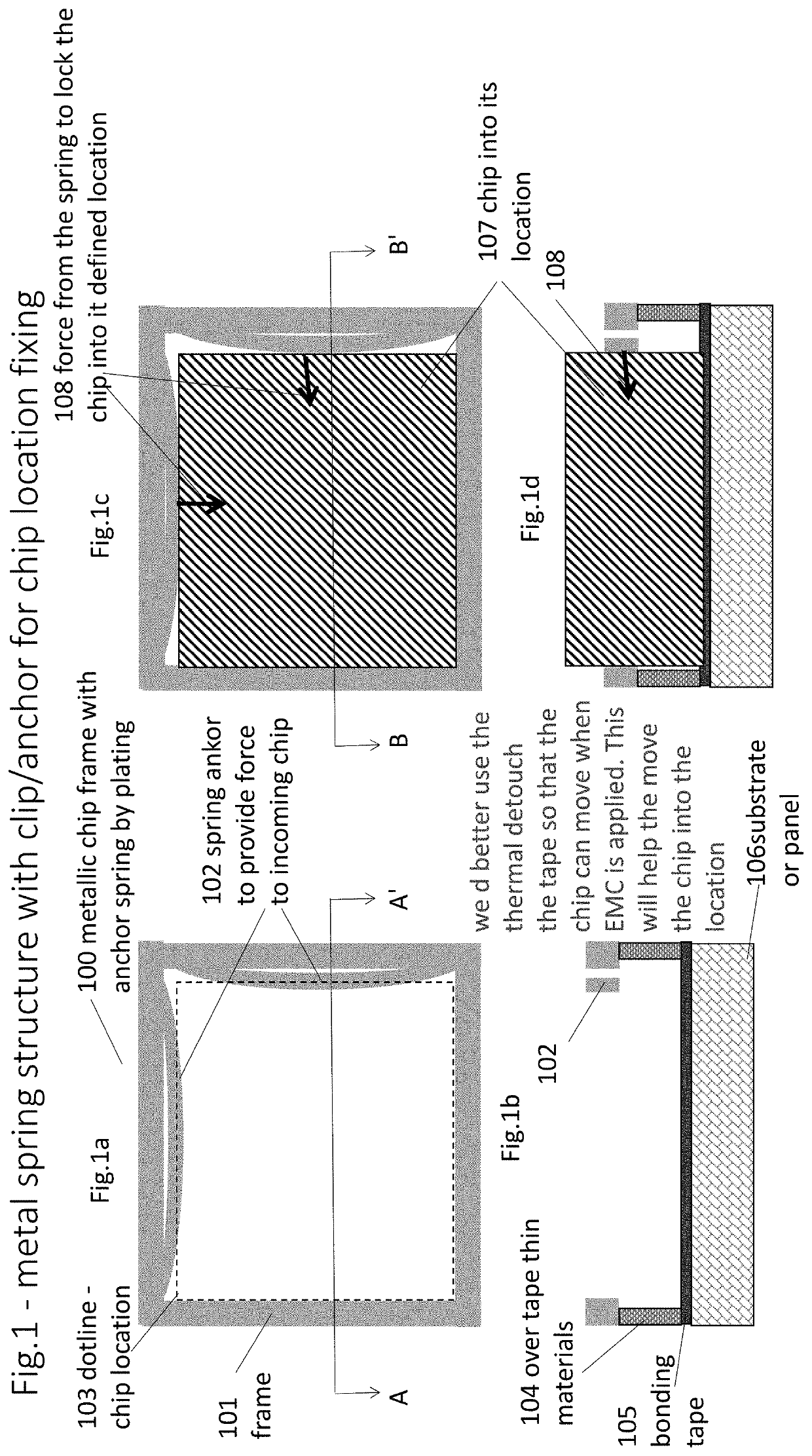
[0039]FIG. 1(a) shows a a projection view of the proposed frame structure with metallic spring / anchor feature on top of a panel or a wafer for an incoming chip location fixing without a die inside. Here, only one structure for a single chip is shown to illustrate the idea of the invention. In this figure, the structure 100. which is on top of a wafer or a panel for FOWLP or FOPLP respectively, is a frame with metal spring feature as a chip anchor. As mentioned previously, the frame can be made of either metallic or dielectric materials. In this particular case, the frame is made of the same ...


PUM


Abstract

An Fan-out packaging system, comprising dedicated frame with associated movable metallic spring feature(s) for incoming known-good-die (KGD), is invented. The movable spring anchor(s) along with the boundaries of the frame locks the KGD in its designated position during EMC implementation and subsequent processes. In this system/approach, the position accuracy of KGDs during the wafer reconstitution process will be mostly dominated by the dicing accuracy. The proposed system is a very low cost approach as it does not need the expensive software/tool set and does not have a low throughput site-to-site lithography correction during exposure after metrology is carried out for every flash field. This system is particularly useful for chiplet consisting of component chips from different technologies and from substrate made of different material. The frames can be further used as part of function component for the packaged system either as electromagnetic shield, or heat dissipation/heat sink, or even RF antenna as well as other passive devices or active components.

Description

RELATED U.S. APPLICATION DATA[0001]Provisional application No. 62 / 972,739, filed on Feb. 11, 2020.FIELD OF INVENTION[0002]The invention is related to advanced packaging, particularly, fan-out panel-level package (FOPLP) or fan-out wafer level package (FOWLP).BACKGROUND ART[0003]Advanced packaging demands low cost, high performance and improved reliability. It is widely believed that FOPLP and FOWLP just can meet these requirements. The two fan out technologies provides space for redistributed I / O connections as well as flexibility, which is particularly important for homogeneous and heterogeneous integration such as chiplet.[0004]Both FOPLP and FOWLP needs reconstitution process, in which dies are placed onto their designated grid locations either on a panel (for FOPLP) or on a wafer (for FOWLP). However, displacement up to 50 um from the nominal location of die can happen during reconstitution in the epoxy molding compound process or even sometimes during subsequent process steps. ...

Claims


Application Information

Patent Timeline
IPC IPC(8): H01L21/687H01L21/68
CPCH01L21/68721H01L21/68H01L21/6715H01L21/68785H01L21/68757H01L21/67333H01L21/565H01L23/3121H01L23/16
Inventor LI, DONGYI, GE
Owner LI DONG
Why Eureka
Try Eureka