Gear device and robot
- Summary
- Abstract
- Description
- Claims
- Application Information
AI Technical Summary
Problems solved by technology
Method used
Image

Examples
first embodiment
2.1. First Embodiment
[0032]A gear device according to a first embodiment is explained.
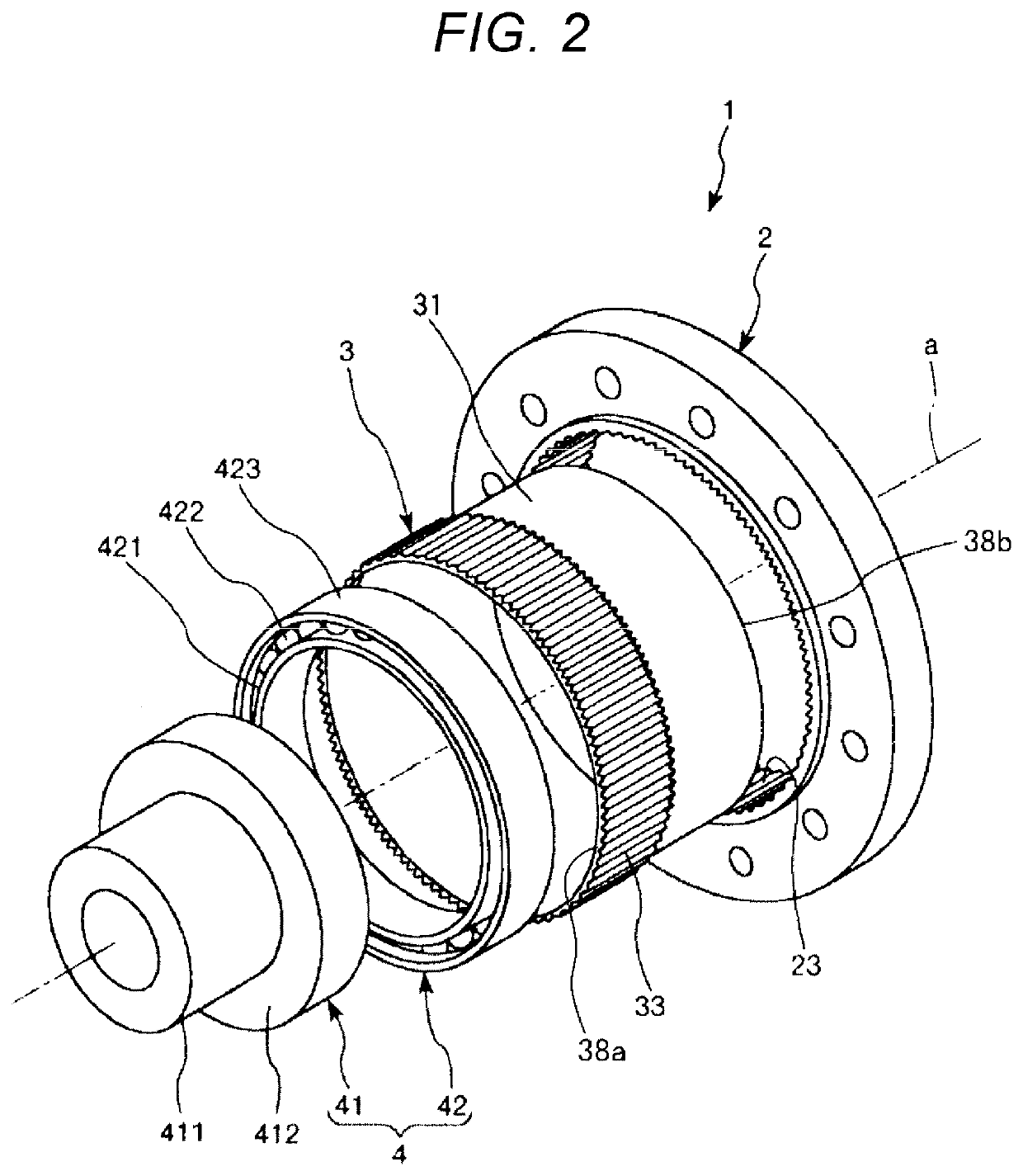
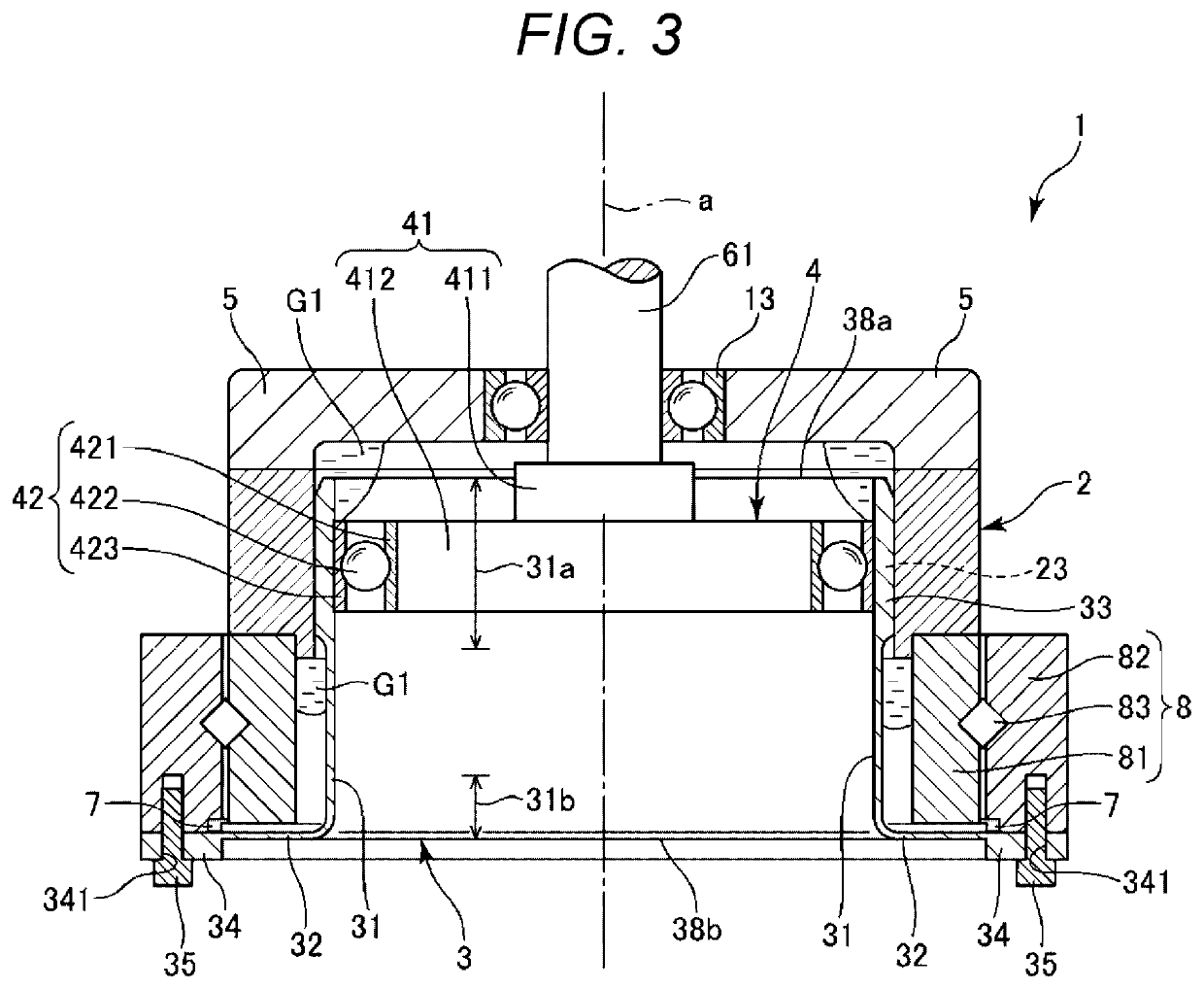
[0033]FIG. 2 is an exploded perspective view showing the gear device according to the first embodiment. FIG. 3 is a longitudinal sectional view of the gear device shown in FIG. 2. FIG. 4 is a front view of the gear device shown in FIG. 2. In the figures, for convenience of explanation, dimensions of sections are exaggerated and shown as appropriate according to necessity. Dimension ratios among the sections and actual dimension ratios do not always coincide. In FIG. 2, for convenience of illustration, a diaphragm section 32 and a boss section 34, which are parts of an external gear 3, are omitted.
[0034]The gear device 1 shown in FIG. 2 is a wave gear device and is used as, for example, a speed reducer. The gear device 1 includes an internal gear 2, the external gear 3 provided on the inner side of the internal gear 2, and a wave generator 4 provided on the inner side of the external gear 3 and incl...
second embodiment
2.2 Second Embodiment
[0086]A gear device according to a second embodiment is explained.
[0087]FIG. 7 is a partially enlarged sectional view showing the gear device according to the second embodiment.
[0088]The second embodiment is explained below. In the following explanation, differences from the first embodiment are mainly explained and explanation about similarities to the first embodiment is omitted.
[0089]A gear device 1A shown in FIG. 7 is the same as the gear device 1 shown in FIG. 5 except that the configuration of the seal section 7 is different.
[0090]The seal section 7 shown in FIG. 7 includes a third seal 73 in addition to the first seal 71 and the second seal 72. The third seal 73 projects from the first seal 71 and is in contact with a bottom surface 812 of the inner ring 81. Specifically, a proximal end 731 of the third seal 73 is fixed to the first seal 71. A distal end 732 of the third seal 73 is in contact with the bottom surface 812 of the inner ring 81. By providing ...
third embodiment
2.3. Third Embodiment
[0098]A gear device according to a third embodiment is explained.
[0099]FIG. 8 is a partially enlarged sectional view showing the gear device according to the third embodiment.
[0100]The third embodiment is explained below. In the following explanation, differences from the first embodiment are mainly explained. Explanation about similarities to the first embodiment is omitted.
[0101]A gear device 1B shown in FIG. 8 is the same as the gear device 1 shown in FIG. 5 except that the configuration of the seal section 7 is different.
[0102]In the seal section 7 shown in FIG. 8, the first seal 71 and the second seal 72 are separated.
[0103]The first seal 71 shown in FIG. 8 is formed in a ring shape, a lateral sectional shape of which is circular. That is, the first seal 71 is a so-called O-shaped ring. The first seal 71 is sandwiched in the gap 340 between the boss section 34 and the outer ring 82 and compressed in the up-down direction in FIG. 8. Consequently, it is possi...
PUM
 Abstract
Description
Claims
Application Information
 - R&D Engineer
- R&D Manager
- IP Professional
- Industry Leading Data Capabilities
- Powerful AI technology
- Patent DNA Extraction
Browse by: Latest US Patents, China's latest patents, Technical Efficacy Thesaurus, Application Domain, Technology Topic.
© 2024 PatSnap. All rights reserved.Legal|Privacy policy|Modern Slavery Act Transparency Statement|Sitemap