
System and method for changing liners, the configuration of which allows the automated removal and insertion of liners of a mill used for ore grinding

a technology for ore grinding mills and liners, which is applied in the field of replacement of wear elements, can solve the problems of reducing effective working times, affecting the efficiency of grinding, and affecting the operation of grinding mills, so as to improve the efficiency of grinding mills, and improve the degree of precision. the effect of method

Pending Publication Date: 2022-03-03
MI ROBOTIC SOLUTIONS MIRS
View PDF16 Cites 0 Cited by
  • Summary
  • Abstract
  • Description
  • Claims
  • Application Information

AI Technical Summary

Benefits of technology

The present invention provides a system and method for changing liners of a mill. The system and method allow for the automated robotic manipulation of mill liners in grinding processes. This results in improved efficiency, accuracy, and reduced downtime for maintenance. The system is safe and removes staff from inside the mill, which is important from a safety perspective.

Problems solved by technology

Liners are subjected to constant wear due to the impact of ore and grinding means (steel balls) thereon, so they must be changed periodically.
Liners are usually changed using remotely controlled manipulation equipment which requires operators to be inside the mill to help in positioning and guiding the liners, with this being a high-risk process for the staff intervening in the changing operation, as well as incurring a great deal of time associated with the maintenance operation.
The method for changing liners in the mill requires the mill to be rotated several times, which entails a lockout-tagout method for motors moving the mill, reducing effective working times, despite the liner manipulator being arranged inside the mill at all times during this operation.
The methods and equipment used in the art for the liner changing process have a series of drawbacks and problems impacting production, as well as the occupational health and safety of the staff.
With the equipment and methods used today, the liner changing time lasts for several days where it is estimated that, on average, the changing of liners is performed at a speed of 5 to 6 liners per hour, which reduces mill availability.
The low speed of conventional equipment used today in the art that is in the order of 1 to 2 rpm prevent said equipment from being more efficient in the time used for performing the maintenance task.
Moreover, in practical terms, as regards maintenance, a weak fixing of liners in the bolts will cause the loosening thereof, favoring pulp leakages, and therefore contamination leaking from the mill to the outside, and it will also cause liners to fall, and therefore unscheduled halting and production loss.
The current method generally involves the staff going into the mill, which is intrinsically risky, working at height, and being exposed to the possibility of the ore or manual tools falling from the mill itself, among others.
The maintenance staff must intervene in the handling of the liners in order to change said liners, which is very physically demanding and involves the risks of getting hit or trapped while removing and inserting liners.
Moreover, the visibility of the operator of the conventional machine and of the maintenance staff is very low inside the mill, which may lead to a lack of coordination.
All these activities involve a high risk, since the machine may hit against operators or operators may be hit by liners, situations that may be fatal should they occur.
However, it makes no reference to equipment which allows performing the tasks for the automated removal and insertion of liners from / into the mill with the appropriate instruments and control.

Method used


Image

  • System and method for changing liners, the configuration of which allows the automated removal and insertion of liners of a mill used for ore grinding
  • System and method for changing liners, the configuration of which allows the automated removal and insertion of liners of a mill used for ore grinding
  • System and method for changing liners, the configuration of which allows the automated removal and insertion of liners of a mill used for ore grinding

Examples


Embodiment Construction

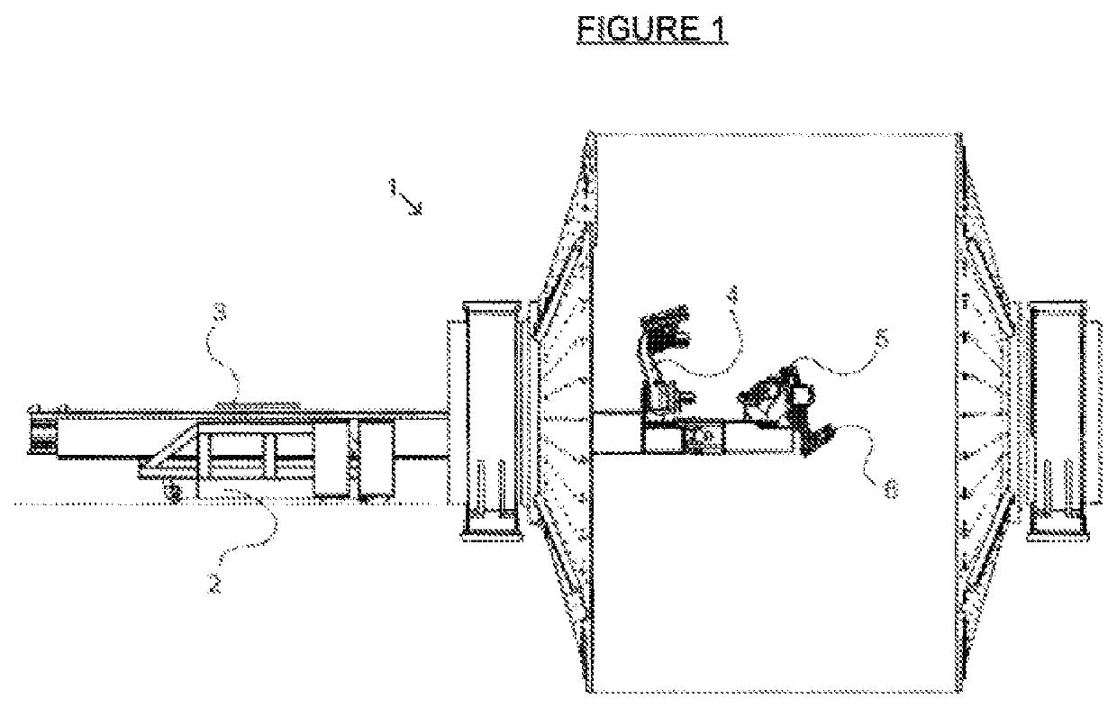
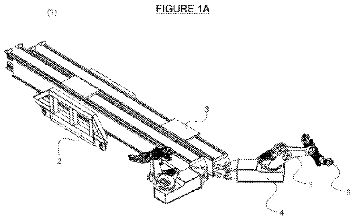
[0063]The invention consists of a system and method for changing liners (1), the configuration of which allows the automated removal and installation of liners of a mill used for grinding ore, as schematically illustrated in FIGS. 1 and 1a, comprising at least one support structure (2), at least one system (3) for supplying and moving liners, at least one robotic manipulator system (4) for manipulating the liners, at least one liner manipulation tool (5), at least one artificial vision system (6), and at least one control system (7).

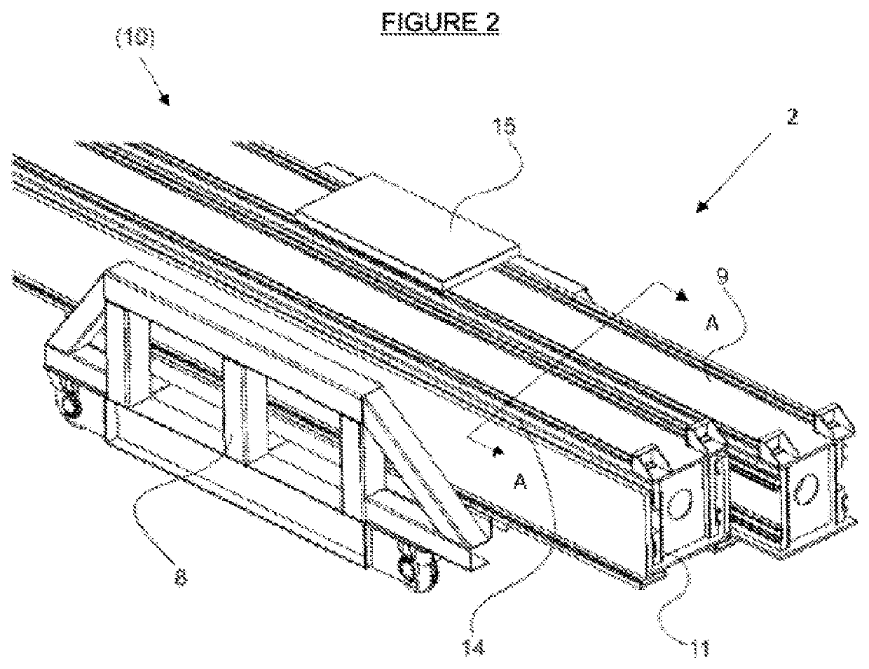
[0064]The support structure (2), illustrated by way of example through FIG. 2, comprises at least one support body or base (8), which allows holding, supporting, and positioning the system for changing liners in a location adjacent to the entrance of the mill where liners from the inner surface of the mill will be changed, wherein said support base or body (8) is arranged outside a mill in which there is supported at least one telescopic beam (9) compris...


PUM

PropertyMeasurementUnit
degrees of freedomaaaaaaaaaa

Abstract

The invention relates to a system and method for changing liners of a mill, the configuration of which allows the automated robotic manipulation of liners of mills for ore grinding in comminution processes. The configuration and operation of the system allows the task of manipulation to be improved, having a greater degree of freedom and / or flexibility in its movements, thereby providing a greater degree of certainty and efficiency to the method and thus optimising the time that the mill is halted for maintenance, and also preventing the risks to which maintenance staff may be exposed. The system comprises at least one support structure, at least one system for supplying and moving liners, at least one robotic manipulator system for manipulating the liners, at least one liner manipulation tool, at least one artificial vision system, and at least one control system.

Description

FIELD OF THE INVENTION[0001]The present invention is comprised among equipment associated with mills for ore grinding in the mining industry; the application particularly relates to the replacement of wear elements, such as the liners or shields of a mill.[0002]The invention relates to a system for changing liners or shields in a mill for ore grinding which comprises one or more robotic manipulators to perform the task of removing and reinstalling liners during the changing process.BACKGROUND OF THE INVENTION[0003]Grinding is a process which allows reducing the size of the ore used in processes of a mining site concentrating plant, in which one of the types of equipment used in grinding is the so-called semi-autogenous grinding mill or SAG mill, the inner surface of which is lined with liners or shields of a different type and shape, according to their location on the inner surface of the mill.[0004]Liners are subjected to constant wear due to the impact of ore and grinding means (s...

Claims


Application Information

Patent Timeline
Patent Type & Authority Applications(United States)
IPC IPC(8): B02C17/18B23P19/02B25J5/02B25J9/06B25J19/04B02C17/22
CPCB02C17/18B23P19/02B02C17/22B25J9/06B25J19/04B25J5/02B23P19/04B25J11/00B23P6/00G05B2219/40071G05B2219/45058G05B2219/45094B25J9/0009B25J19/023G05B2219/39G05B2219/40
Inventor SALAMANCA POBLETE, HUGOBAEZA RAMIREZ, LUIS
Owner MI ROBOTIC SOLUTIONS MIRS
Learn More