Controller for vehicle

a controller and vehicle technology, applied in the direction of propulsion parts, propulsion using engine-driven generators, transportation and packaging, etc., can solve the problems of giving a driver a feeling of discomfort, and the implementation of this control is not preferable from the viewpoint of improving electric efficiency, so as to improve the response delay

Pending Publication Date: 2022-03-03
MITSUBISHI MOTORS CORP
View PDF0 Cites 0 Cited by
  • Summary
  • Abstract
  • Description
  • Claims
  • Application Information

AI Technical Summary

Benefits of technology

[0014]According to the disclosed controller, a response delay for engagement of the connecting / disconnecting mechanism since an accelerator pedal has been depressed, for example, can be compensated by the driving power of the second rotating electric machine. Therefore, it is possible to improve the response delay at the time of engagement of the connecting / disconnecting mechanism.

Problems solved by technology

If the induced voltage generated by this corotation of the motor exceeds the voltage of the driving-purpose battery, the regenerative brake will be activated on the vehicle, which may give a driver a feeling of discomfort.
However, since the implementation of the flux-weakening control consumes electric power, implementation of this control is not preferable from the viewpoint of improvement in electric efficiency.

Method used


Image

  • Controller for vehicle
  • Controller for vehicle
  • Controller for vehicle

Examples


Embodiment Construction

[0022]Description will now be made in relation to a controller for a vehicle according to an embodiment with reference to the accompanying drawings. The following embodiment is merely illustrative and is not intended to exclude the application of various modifications and techniques not explicitly described in the embodiment. Each configuration of the present embodiment can be variously modified and implemented without departing from the scope thereof. Also, the configuration can be selected or omitted according to the requirement or appropriately combined.

1. Overall Configuration

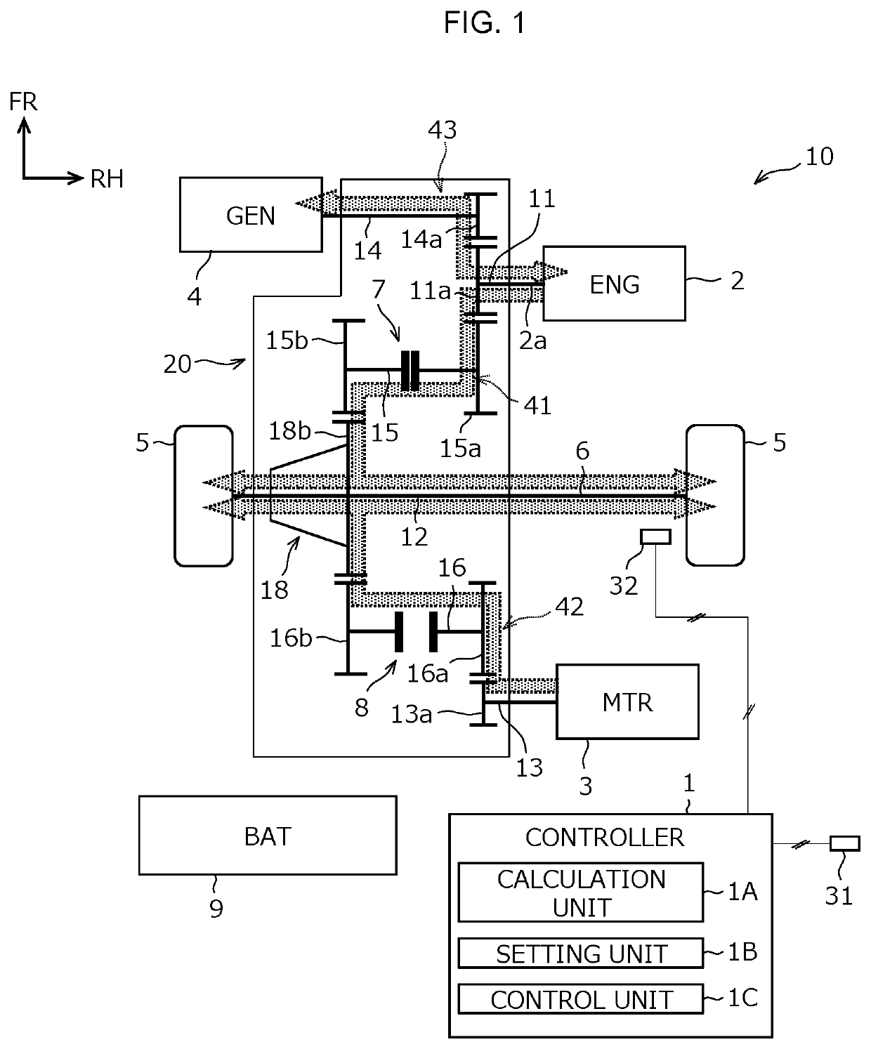
[0023]A controller 1 of this embodiment is applied to a vehicle 10 shown in FIG. 1, and controls an engine 2, a motor 3, a generator 4, clutches 7 and 8, and the like mounted on the vehicle 10. This vehicle 10 is a hybrid vehicle equipped with the engine 2 serving as a driving source, the motor 3 (first rotating electric machine) for running, and the generator 4 (second rotating electric machine) for power ...


PUM


Abstract

A vehicle (10) has mounted therein an engine (2), a first rotating electric machine (3), and a second rotating electric machine (4). The power of the engine (2) and the power of the first rotating electric machine (3) are separately transmitted from different power transmission paths (41, 42) to drive wheels (5). The power of the engine (2) is also transmitted to the second rotating electric machine (4) and utilized to generate electrical power. The vehicle (10) is provided with a connecting/disconnecting mechanism (8) on the power transmission path (42) that transmits the power of the first rotating electric machine (3) to the drive wheels (5). A controller (1) of the vehicle (10) calculates a requested driving power of the vehicle (10), and when the connecting/disconnecting mechanism (8) is shifted from a disengaged state to an engaged state to deal with an increase in the requested driving power while the engine (2) is running, makes the second rotating electric machine (4) power run and transmits power of the second rotating electric machine (4) to the drive wheels (5).

Description

TECHNICAL FIELD[0001]This disclosure relates to a controller for a vehicle provided with an engine and a first rotating electric machine, each serving as a driving source, and a second rotating electric machine that generates power using power of the engine.BACKGROUND ART[0002]Conventionally, a hybrid vehicle equipped with an engine and a rotating electric machine (motor, generator, motor generator) and also runs while switching its running mode has been practically used. The running mode includes: an EV mode in which the vehicle runs only on the motor using the charged power of a battery; a series mode in which the vehicle runs only on the motor while the generator is made to generate electricity by the engine; and a parallel mode that the vehicle runs mainly on the engine while being assisted by the motor if needed.[0003]In the hybrid vehicle capable of individually outputting the power of the engine and the power of the motor, a power transmission path from the engine to the driv...

Claims


Application Information

Patent Timeline
Patent Type & Authority Applications(United States)
IPC IPC(8): B60W20/40B60K6/485
CPCB60W20/40B60Y2200/92B60K6/485B60W10/08B60K6/442B60L50/16B60L50/15B60W10/02Y02T10/62Y02T10/72B60K6/387B60W10/06B60W20/30B60W2710/086B60W2520/10B60W2540/10
Inventor ABE, HIRONORIHANDA, KAZUNORIOGINO, DAIZOTAKEUCHI, HITOSHI
Owner MITSUBISHI MOTORS CORP
Why Eureka
Try Eureka