Vehicle control device

A control device and vehicle technology, applied to control devices, power devices, vehicle components, etc., can solve problems such as time-consuming and inability to complete the connection immediately, and achieve the effect of improving response delay

Active Publication Date: 2021-08-17
MITSUBISHI MOTORS CORP
View PDF12 Cites 0 Cited by
  • Summary
  • Abstract
  • Description
  • Claims
  • Application Information

AI Technical Summary

Problems solved by technology

[0009] However, in a vehicle equipped with the above-mentioned clutch, even if the connection of the clutch in the disengaged state is started, the connection cannot be completed immediately, so there is a technical problem that it takes time until the power of the motor can be transmitted to the drive wheels.
That is, in a situation where motor assistance is required, a response delay occurs, so there is still room for improvement regarding the connection of the clutch.

Method used


Image

  • Vehicle control device
  • Vehicle control device
  • Vehicle control device

Examples


Embodiment Construction

[0027] A control device for a vehicle as an embodiment will be described with reference to the drawings. The embodiments shown below are merely examples, and it is not intended to exclude various modifications and technical applications not explicitly described in the following embodiments. Each structure of this embodiment can be variously modified and implemented in the range which does not deviate from these summary. In addition, trade-offs can be made as necessary, or appropriate combinations can be made.

[0028] [1. Overall structure]

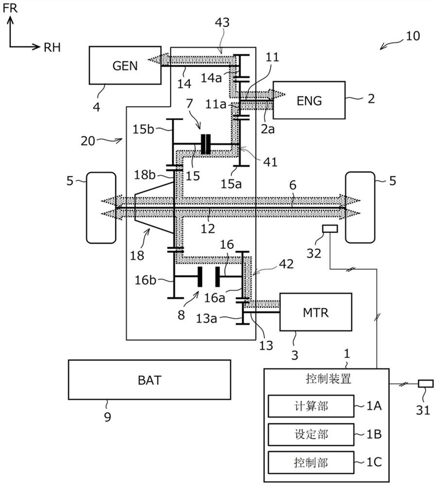
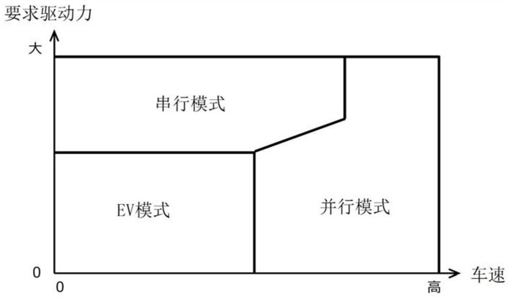
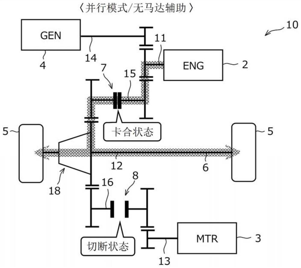
[0029] The control device 1 of this embodiment is applied to figure 1 The illustrated vehicle 10 controls an engine 2 , a motor 3 , a generator 4 , clutches 7 , 8 , and the like mounted on the vehicle 10 . This vehicle 10 is a hybrid vehicle equipped with an engine 2 as a drive source, a motor 3 for traveling (first rotating electrical machine), and a generator 4 for generating electricity (second rotating electrical machine). In addi...


PUM


Abstract

A vehicle (10) has mounted therein an engine (2), a first rotating electrical machine (3), and a second rotating electrical machine (4). The power of the engine (2) and the power of the first rotating electrical machine (3) are separately transmitted from different power transmission paths (41, 42) to drive wheels (5). The power of the engine (2) is also transmitted to the second rotating electrical machine (4) and utilized to generate electrical power. The vehicle (10) is provided with an engagement-disengagement mechanism (8) on the power transmission path (42) that transmits the power of the first rotating electrical machine (3) to the drive wheels (5). A control device (1) of the vehicle (10) calculates the drive power required of the vehicle (10). When shifting the engagement-disengagement mechanism (8) from a disengaged state to an engaged state as a result of an increase in the required drive power during driving of the engine (2), the control device (1) causes power running of the second rotating electrical machine (4) and transmits the power of the second rotating electrical machine (4) to the drive wheels (5).

Description

technical field [0001] The present invention relates to a control device for a vehicle equipped with an engine as a drive source, a first rotating electrical machine, and a second rotating electrical machine that generates power from the power of the engine. Background technique [0002] Conventionally, among hybrid vehicles equipped with an engine and a rotary electric machine (motor, generator, motor generator), a vehicle that travels while switching travel modes has been put into practical use. The driving mode includes: EV mode in which the motor runs only by using the charging power of the battery, a serial mode in which the motor runs only by the motor while the generator is generating electricity through the engine, and a motor that drives by the main body of the engine and is assisted by the motor when necessary. Parallel mode etc. [0003] In a hybrid vehicle capable of independently outputting the power of the engine and the power of the motor, a power transmissio...

Claims


Application Information

Patent Timeline
Patent Type & Authority Applications(China)
IPC IPC(8): B60W20/40B60K6/442B60W10/02B60W10/04B60W10/08B60L50/15B60L50/16
CPCB60W10/08B60W20/40B60K6/442B60L50/16B60L50/15B60W10/02Y02T10/62Y02T10/72B60K6/387B60W10/06B60W20/30B60W2710/086B60W2520/10B60W2540/10B60K6/485B60Y2200/92
Inventor 安部洋则半田和功荻野大藏竹内均
Owner MITSUBISHI MOTORS CORP
Why Eureka
Try Eureka