
Pallet module, assortment of pallet modules, and pallet assembly built of the same

a pallet module and pallet technology, applied in the field of pallet modules, can solve the problems of selective manual release of the foot element, prone to breakage, and potential disconnection of the pallet module, and achieve the effects of boosting efficiency and ease of use, facilitating assembly (and disassembling) very easily and quickly, and ensuring stability

Pending Publication Date: 2022-03-03
PONERA GRP SAGL
View PDF0 Cites 0 Cited by
  • Summary
  • Abstract
  • Description
  • Claims
  • Application Information

AI Technical Summary

Benefits of technology

The present invention aims to provide a pallet module that can create a strong and durable pallet assembly while also being easy and fast to assemble and disassemble. The use of standardized pallet modules allows for the creation of pallet assemblies of various sizes, reducing costs and allowing for better space usage. Additionally, a circular economy can integrate digital solutions to manage and track individual pallet modules efficiently.

Problems solved by technology

While this solution is suitable for forming a nested pallet assembly of at least two pallet modules, the resulting pallet assembly is however insufficiently robust, the mating and interlocking system being prone to undesired release, leading to potential disconnection of the pallet modules during handling and / or transport of loads, which is clearly undesirable.
The interlocking system contemplated in U.S. Pat. No. 3,857,342 A is furthermore prone to breakage after repeated uses due to the inherent local deformations of the plastic material at the points of attachment between the pallet modules.
However, once the foot element has been fully inserted into its mounting location, it is irreversibly secured to the lower side of the pallet by the spring-loaded locking mechanism, thus preventing selective manual release of the foot element.
These other known solutions likewise have drawbacks, including complex nesting and / or interlocking systems that unnecessarily complicate assembly and disassembly of multiple pallet modules one with, respectively from the other, which leads to reduced efficiency in usage.
A further problem with the aforementioned known pallet modules resides in that they are not optimized for shipment or warehousing of the individual pallet modules and components, especially due to the presence of feet that are typically made integral with a main structural body of the pallet module.
This known solution may furthermore restrict the ability to stack individual pallet modules one on top of the other in a compact manner.
Another problem with the known pallet modules resides in the lack of flexibility thereof, especially in terms of sizes and dimensions which are not optimal and restrict the user's ability to build a large variety of pallet assemblies of varying sizes and dimensions for non-standard size goods or equipment.
Furthermore, the height of the known pallet modules, and of the resulting pallet assemblies, is not optimized and the configuration thereof typically restricts the ability to use the full volume of the transport units and / or to efficiently stack individual pallet modules one above the other for e.g. shipment or warehousing purposes.
Even though these wooden pallets can be produced in basically any sizes, and can be regarded as providing a reasonably flexible solution, they do not constitute an efficient solution for end users due to the fact that they are produced to meet specific needs and are typically intended for single use, which makes this solution cost inefficient and environmentally non-sustainable.
As far as standard-size Euro-pallets are concerned, these are cheap to produce but, overall, their fixed size of 1200 mm×800 mm×144 mm (length×width×height) is not optimal when it comes to shipping and / or warehousing individual pallets and / or for the packaging and shipment of goods or equipment requiring a specific, non-standard pallet solution.
As a matter of fact, such standardized or semi-standardized pallet solutions only allow to exploit at most of the order of 80% to 90% of the available shipping space of a standard dry container (be it 20 feet or 40 feet in length), which leads to huge inefficiencies and substantial waste in shipping space.
The existing solutions do not therefore provide flexibility and adaptability in terms of pallet sizes, which is important for transport, packaging and cost efficiency.
Conventional wooden pallets are furthermore not very robust and are prone to breakage, meaning that their usability and life cycle is typically limited to single use or at best to only a few usage cycles (typically less than five times on average).
Standard-sized pallets like the Euro-pallets do not furthermore constitute an optimal solution for shipment of goods or equipment having non-standard sizes and dimensions.

Method used


Image

  • Pallet module, assortment of pallet modules, and pallet assembly built of the same
  • Pallet module, assortment of pallet modules, and pallet assembly built of the same
  • Pallet module, assortment of pallet modules, and pallet assembly built of the same

Examples


first embodiment

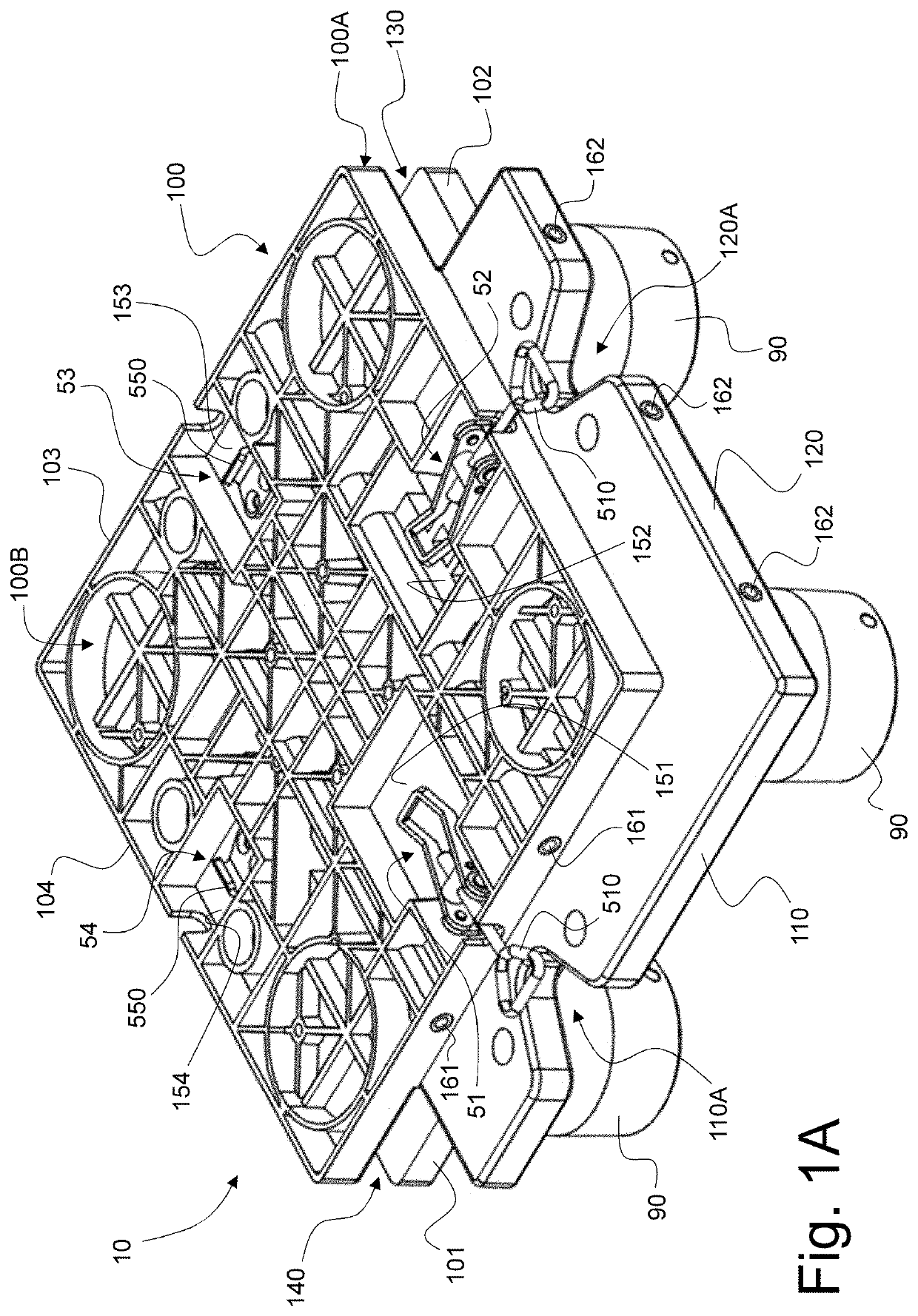
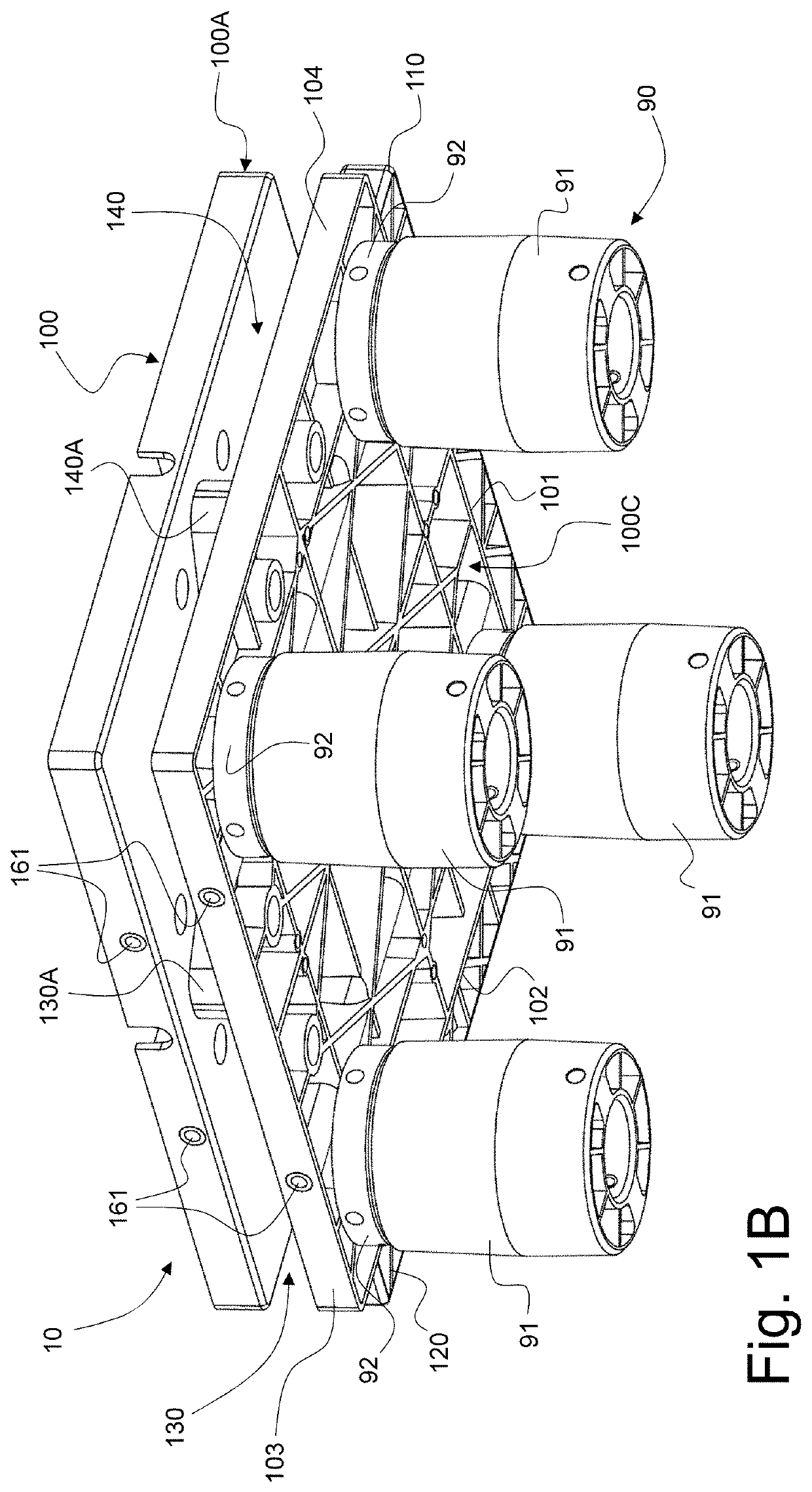
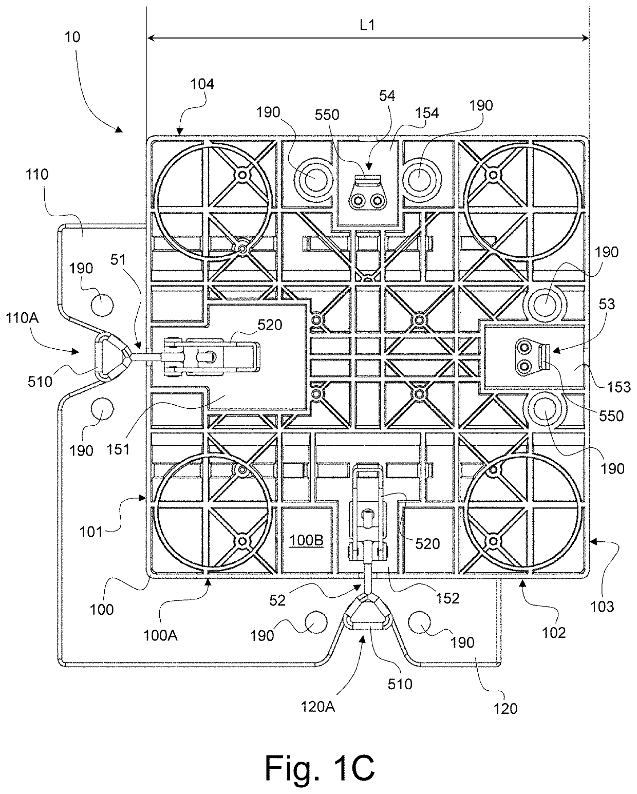
[0088]FIGS. 1A and 1B are two perspective views, taken from different viewing angles, of a pallet module, designated globally by reference numeral 10, in accordance with the invention. The same pallet module 10 is shown from the top and bottom in FIGS. 1C and 1D and from all four sides in FIGS. 1E to 1H.

[0089]The pallet module 10 (as well as the other embodiments of pallet modules described herein) is configured to allow formation of a nested pallet assembly of at least two similar pallet modules, be it another identical pallet module 10 or e.g. a compatible pallet module 20 or 30 as for instance shown in FIGS. 3A-C or FIGS. 4A-C.

[0090]The pallet module 10 comprises a main structural body 100 exhibiting a generally quadrilateral peripheral border 100A with first to fourth lateral sides 101-104 extending between upper and lower sides 100B, 100C of the main structural body 100. The first to fourth lateral sides 101-104 are here numbered in sequence in the counter-clockwise direction w...

second embodiment

[0114]FIGS. 3A-C are two perspective views, taken from different viewing angles, and a top view of a pallet module, designated globally by reference numeral 20, in accordance with the invention, and which forms part of a same assortment of pallet modules as the pallet module 10 of FIGS. 1A-H. The pallet module 20 will also be referred as a “large-size pallet module”.

third embodiment

[0115]FIGS. 4A and 4B are two perspective views, taken from different viewing angles, and a top view of a pallet module, designated globally by reference numeral 30, in accordance with the invention, and which likewise forms part of a same assortment of pallet modules as the pallet module 10 of FIGS. 1A-H and the pallet module 20 of FIGS. 3A-C. The pallet module 30 will also be referred as a “medium-size pallet module”.

[0116]The pallet modules 20 and 30 share a substantial number of common features with the pallet module 10, including:[0117]a main structural body 200, resp. 300, exhibiting a generally quadrilateral peripheral border 200A, resp. 300A with first to fourth lateral sides 201-204, resp. 301-304, extending between upper and lower sides 200B, 200C, resp. 300B, 300C, of the main structural body 200, resp. 300;[0118]first and second lateral flanges 210, 220, resp. 310, 320, extending outwardly from the peripheral border 200A, resp. 300A, of the main structural body 200, resp...


PUM


Abstract

A pallet module configured to allow formation of a nested pallet assembly of at least two similar pallet modules, including a main structural body having a generally quadrilateral peripheral border with first to fourth lateral sides, first and second lateral flanges extending outwardly from the peripheral border along the first and second lateral sides and configured to cooperate with first and second lateral grooves extending inwardly from the peripheral border along the third and fourth lateral sides of another similar pallet module to form the nested pallet assembly, a foot structure disposed on a lower side of the main structural body, and first and second toggle latch components arranged in the vicinity of the first and second lateral sides, respectively, configured to cooperate and releasably interlock with third and fourth toggle latch components arranged in the vicinity of the third and fourth lateral sides, respectively, of another similar pallet module.

Description

TECHNICAL FIELD[0001]The present invention generally relates to a pallet module configured to allow formation of a nested pallet assembly of at least two similar pallet modules, which nested pallet assembly is configured to act as a self-supporting platform allowing the handling and transportation of goods. The invention also relates to an assortment of such pallet modules produced in at least two different sizes, as well as to a pallet assembly built of multiple such pallet modules which are nested within and interlocked with one another.BACKGROUND OF THE INVENTION[0002]U.S. Pat. No. 3,857,342 A discloses a pallet formed of nestable plastic modules each having four centrally located legs and four outwardly extending flanges, with each of the flanges having means for interlocking with the flanges of adjacent modules. While this solution is suitable for forming a nested pallet assembly of at least two pallet modules, the resulting pallet assembly is however insufficiently robust, the...

Claims


Application Information

Patent Timeline
Patent Type & Authority Applications(United States)
IPC IPC(8): B65D19/00
CPCB65D19/0051B65D2519/00034B65D2519/00069B65D2519/00746B65D2519/00338B65D2519/00407B65D2519/00412B65D2519/00129B65D19/004B65D19/0097B65D2519/00268B65D2519/00273B65D2519/00288B65D2519/00293B65D2519/00318B65D2519/00323B65D2519/00437B65D2519/00567B65D2519/00572Y02W30/80B65D19/40B65D2519/00308B65D2519/0094
Inventor REALI, MATTHEWTALEBI AMIRI, MASOUD
Owner PONERA GRP SAGL
Learn More