
Bauschinger effect test fixture

a test fixture and bauschinger technology, applied in the field of material performance research, can solve the problems of fixture failure to provide an ultrasonic detection probe to detect the stress on the test piece, the piece to be bent and buckling, and the test cannot be completed

Active Publication Date: 2022-03-03
BEIJING INSTITUTE OF TECHNOLOGYGY
View PDF4 Cites 0 Cited by
  • Summary
  • Abstract
  • Description
  • Claims
  • Application Information

AI Technical Summary

Benefits of technology

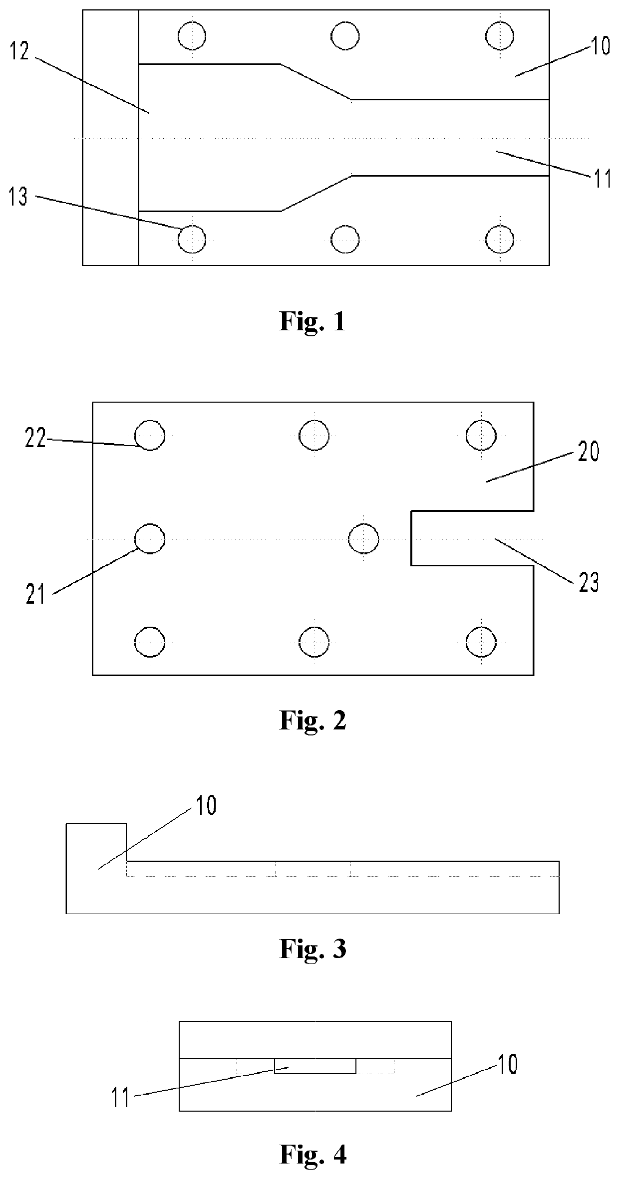
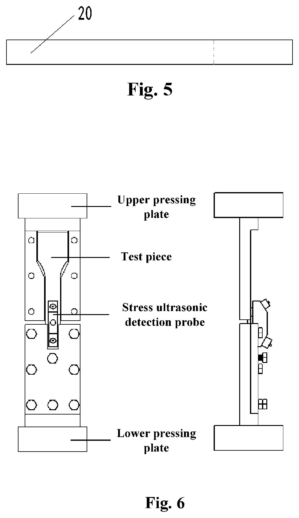
The present disclosure describes a Bauschinger effect test fixture for compressing a test piece to verify its material properties. The fixture consists of two identical split bodies with limiting grooves that correspond to the shape of the test piece. The test piece is placed in the limiting grooves and fixedly connected to the fixture through bolts to ensure that it cannot slide. The fixture is installed on a test machine for stretching and compressing materials and applies compression force. The stress ultrasonic detection probe on the test piece detects changes in compression stress during the compression process and when the material is yielded or compressed to failure, thereby verifying the Bauschinger effect of the material. The fixture solves the problem of bending and buckling when the material is subjected to plastic deformation by using the compression function of the test machine.

Problems solved by technology

When a test machine for stretching and compressing materials is used to stretch and compress a strip-shaped metal material test piece to verify Bauschinger effect, the compression of the test piece may cause the test piece to be bent and buckling, so that the test cannot be completed.
The fixture cannot be provided with an ultrasonic detection probe to detect the stress on the test piece, and there is therefore a need to redesign the Bauschinger effect test fixture.

Method used


Image

  • Bauschinger effect test fixture
  • Bauschinger effect test fixture

Examples


Embodiment Construction

[0025]The specific embodiments of the present disclosure, which as a part of this specification illustrate the principles of the present disclosure by way of examples, will be described in detail below with reference to the accompanying drawings, and other aspects, features and advantages of the present disclosure will become apparent from the detailed description. In the referenced drawings, identical or similar elements in different drawings are designated with identical reference numerals.

[0026]The present disclosure provides a test fixture for Bauschinger effect, which is mainly used for compressing a test piece on a test machine for stretching and compressing materials so as to realize the purpose of verifying the Bauschinger effect of the material, wherein the test piece usually has a strip-shaped configuration with two wide ends and a narrow middle part. The object targeted by the present disclosure is the test piece, which is bent and buckling when being compressed by the te...


PUM


Abstract

A Bauschinger effect test fixture that cooperates with a test machine for stretching and compressing materials to perform a Bauschinger effect test on a test piece having a symmetrical configuration with two wide ends and a narrow middle part. The fixture includes two identical split bodies, where each split body has a base provided, longitudinally from a central part to one end of the base, with a limiting groove corresponding to a half of the profile of the test piece. Two sides of the groove are arranged symmetrically with a plurality of threaded through holes and a cover is provided along its central axis with two threaded through holes with which the test piece is pressed tightly by bolts. An end of the cover corresponding to a notch of the limiting groove is provided with a through groove configured for placing a stress ultrasonic detection probe on the test piece.

Description

CROSS-REFERENCE TO RELATED APPLICATIONS[0001]This application claims priority to China Patent Application Serial No. 202010870645.6 filed Aug. 26, 2020, the entire disclosure of which is herein incorporated by reference.BACKGROUNDField[0002]The present disclosure relates to the technical field of material performance research, and in particular to a Bauschinger effect test fixture.Discussion of the Related Art[0003]In the process of metal plastic processing, there is a phenomenon that occurs on metal material in that a plastic strain strengthening caused by a forward loading leads a plastic strain softening (reduction in yield limit) during a subsequent reverse loading. This phenomenon was found by J. Bauschinger in the experiments on mechanical properties of the metal material in 1886. When the metal material is first stretched to a plastic deformation stage, then unloaded to zero, and then loaded in reverse, i.e., subjected to compression deformation, the compressive yield limit (...

Claims


Application Information

Patent Timeline
IPC IPC(8): G01N3/04G01N3/08
CPCG01N3/04G01N3/08G01N2203/0003G01N2203/0423G01N2203/0019G01N2203/0658G01N2203/0017G01N2203/0258G01N2203/0676G01N2203/0098G01N2203/0268
Inventor XU, CHUNGUANGLI, SHUANGYIMIAO, ZHAOWEI
Owner BEIJING INSTITUTE OF TECHNOLOGYGY
Learn More