Steering control device

Pending Publication Date: 2022-03-10
JTEKT CORP +2
View PDF0 Cites 0 Cited by
  • Summary
  • Abstract
  • Description
  • Claims
  • Application Information

AI Technical Summary

Benefits of technology

The patent text describes a device that can improve the steering feel of a driver when they perform intervention steering. This means that the device can create a better sensory experience for the driver while in control of the vehicle. Essentially, this invention provides a new way to control steering that results in a better driving experience.

Problems solved by technology

This torque may hinder the driver's steering.
Further, this torque may cause discomfort to the driver.
This configuration can reduce the likelihood that when a second control amount having an excessively large value is calculated, the motor output may become excessively large based on that second control amount having an excessively large value.
When the driver turns the steering wheel backward while the vehicle is turning with the host control device intervening in steering control, this leads to a situation where only the second control amount is restricted and only the third control amount increases.

Method used


Image

  • Steering control device
  • Steering control device
  • Steering control device

Examples


first embodiment

[0046]Next, a first embodiment in which a steering control device is embodied as a control device of an electric power steering system (EPS) will be described.

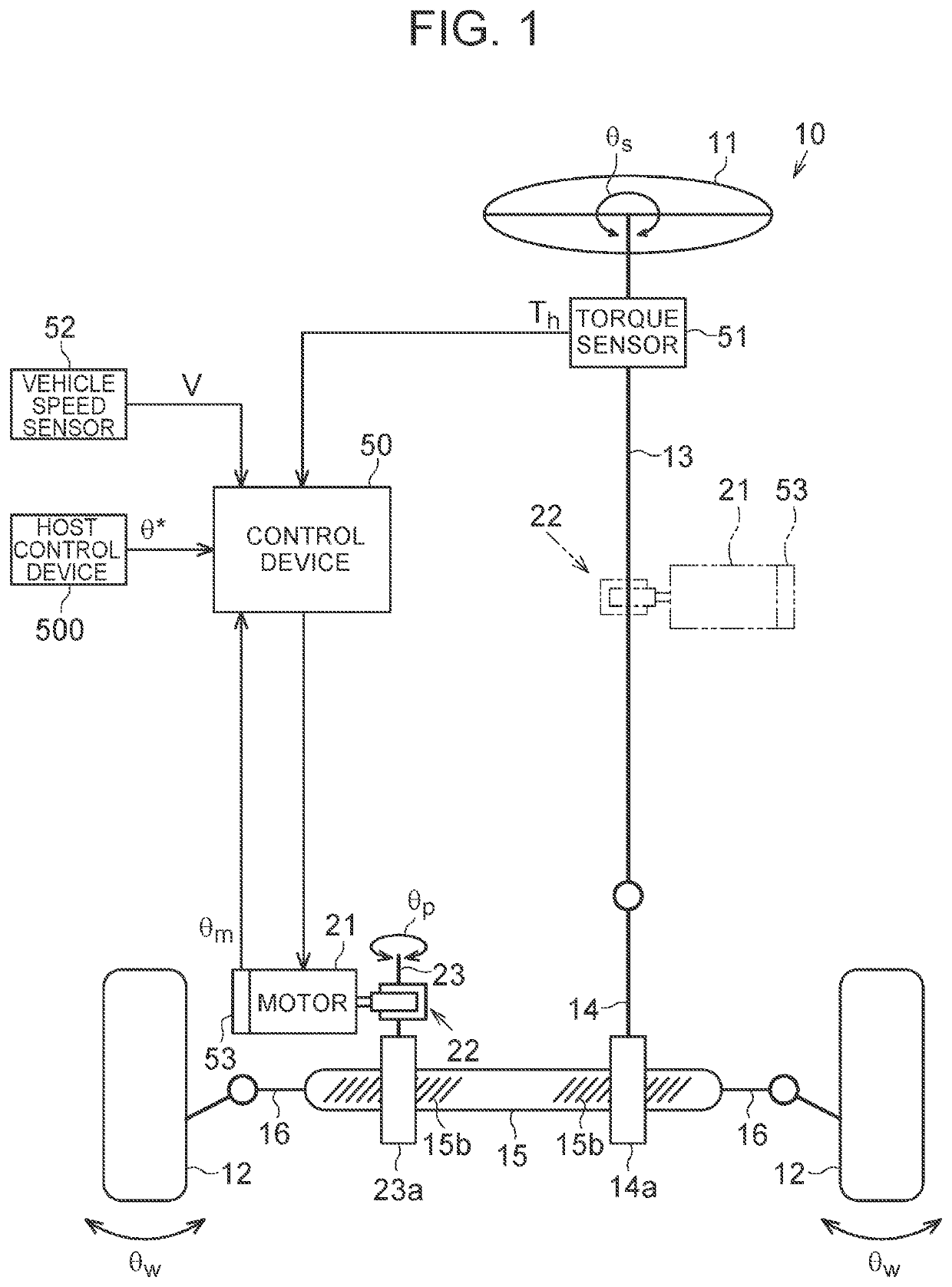
[0047]As shown in FIG. 1, an EPS 10 has a steering shaft 13, a pinion shaft 14, and a turning shaft 15 that function as a power transmission path between a steering wheel 11 and turning wheels 12. The turning shaft 15 extends along a vehicle width direction (a left-right direction in FIG. 1). The turning wheels 12 are respectively coupled at both ends of the turning shaft 15 through tie rods 16. The pinion shaft 14 is provided so as to intersect with the turning shaft 15. Pinion teeth 14a of the pinion shaft 14 are meshed with rack teeth 15a of the turning shaft 15. The turning shaft 15 makes linear motion in conjunction with rotary operation of the steering wheel 11. The linear motion of the turning shaft 15 is transmitted to the left and right turning wheels 12 through the tie rods 16, which changes turning angles θw of the ...

second embodiment

[0066]Next, a second embodiment in which a steering control device is embodied as a control device of an EPS will be described. In the above-describe first embodiment, there is the following concern: When the driver performs intervention steering while the vehicle is turning under automated driving control, the driver may feel discomfort due to the difference in steering feel between turning the steering wheel 11 forward and turning it backward.

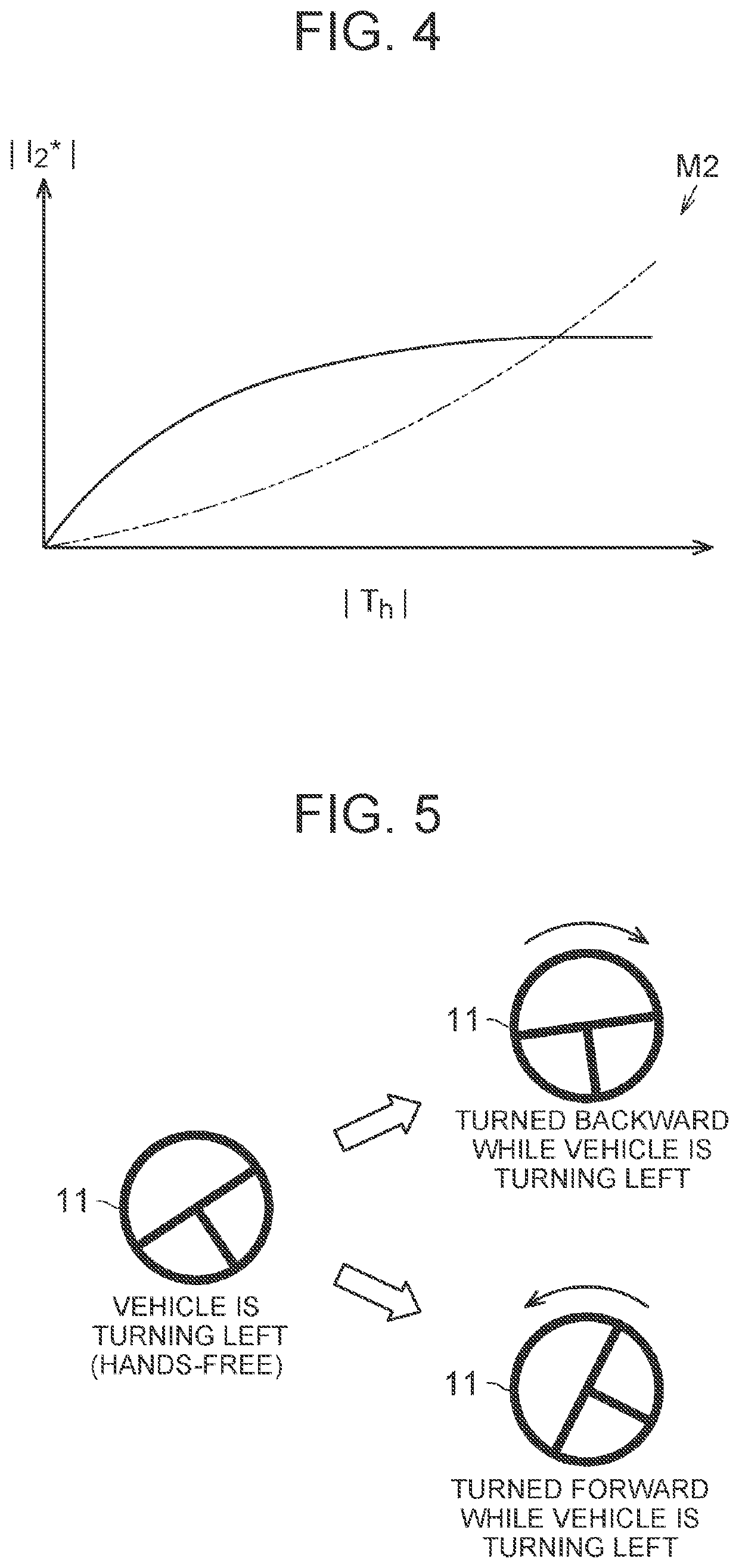
[0067]“Turning forward” refers to a turning state in which the driver is applying a torque to the steering wheel 11 in the same direction as the direction in which the steering wheel 11 is being turned by automated steering. “Turning backward” refers to a turning state in which the driver is applying a torque to the steering wheel 11 in the opposite direction from the direction in which the steering wheel 11 is being turned by automated steering.

[0068]As shown in FIG. 5, for example, when the vehicle is turning left under automated driving co...

third embodiment

[0084]Next, a third embodiment in which a steering control device is embodied as a control device of an EPS will be described. This embodiment differs from the above-described first embodiment in terms of the configuration of the microcomputer 50A.

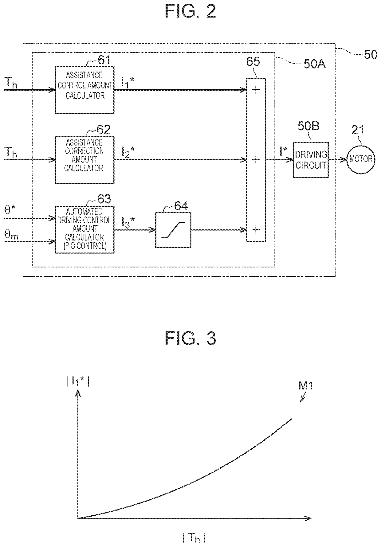
[0085]As shown in FIG. 12, the automated driving control amount calculator 63 has a subtractor 71, a feedforward controller 72, a proportional controller 73, an integral controller 74, a differential controller 75, three adders 76, 77, 78, and two restriction processors 79A, 79B.

[0086]The subtractor 71 calculates the deviation Δθ (=θ*−θm) of the rotation angle θm of the motor 21 detected through the rotation angle sensor 53 from the target angle θ* calculated by the host control device 500. The feedforward controller 72 is provided to compensate for a delay in response due to inertia of the EPS 10 and increase the control responsiveness. The feedforward controller 72 calculates a target angle acceleration rate α (=d2θ* / dt2) by performing s...


PUM


Abstract

A steering control device includes: a first calculator configured to calculate, according to a turning state, a first control amount for causing a motor to generate an assistance force; a second calculator configured to calculate a second control amount for adapting an actual angle to a target angle that is convertible into a turning angle of a steering wheel and generated when a host control device intervenes in steering control; and a third calculator configured to calculate, according to the turning state, a third control amount for offsetting the second control amount when the host control device intervenes in steering control.

Description

CROSS-REFERENCE TO RELATED APPLICATION[0001]This application claims priority to Japanese Patent Application No. 2020-150050 filed on Sep. 7, 2020, incorporated herein by reference in its entirety.BACKGROUND1. Technical Field[0002]The disclosure relates to a steering control device.2. Description of Related Art[0003]For example, the control device of Japanese Unexamined Patent Application Publication No. 2015-20604 executes lane-keep control of causing a vehicle to travel along a lane and assistance control of assisting a driver in steering. The control device generates an assistance command for generating an assistance torque according to a steering torque. Further, the control device generates an adaptation command for generating an automated steering torque according to a target angle set by a host control device. Based on an additional value of the assistance command and the adaptation command, the control device controls electricity supplied to a motor.[0004]When the driver's in...

Claims


Application Information

Patent Timeline
IPC IPC(8): B62D6/10B62D5/04
CPCB62D6/10B62D5/0463B62D6/008B62D6/007B62D15/025B62D1/286
Inventor NITTA, SHINGOTOKO, TAKAHIROKUNIHIRO, YOJIKOJO, TAKAHIROAKATSUKA, HISAYA
Owner JTEKT CORP
Why Eureka
Try Eureka