Aircraft engine

a technology for aircraft engines and propellers, applied in the direction of machines/engines, sustainable transportation, mechanical equipment, etc., can solve the problems of swept blades that are not without challenges, swept blades are more difficult to balance, and shockwaves are chiefly an issu

Active Publication Date: 2022-03-10
ROLLS ROYCE PLC
View PDF3 Cites 0 Cited by
  • Summary
  • Abstract
  • Description
  • Claims
  • Application Information

AI Technical Summary

Problems solved by technology

Such shockwaves are chiefly an issue for high-speed fans, i.e. fans designed for air moving through the fan with a high relative Mach number (Mrel).
Swept blades however are not without their challenges.
Swept blades are more difficult to balance as their curvature affects the centre of gravity of the blade.
It is important to keep excitation frequencies away from blade resonance frequencies, else resonant excitation could lead to reduced blade life.
Complex sweep shapes result in higher manufacturing costs, reducing the incentive to sweep the blade unless necessary.
Increasing the surface area of the nacelle means an increase in the drag experienced by the nacelle, as well as an increase in the nacelle's weight, which means a reduction in engine fuel efficiency.

Method used


Image

  • Aircraft engine
  • Aircraft engine
  • Aircraft engine

Examples


Embodiment Construction

[0031]Aspects and embodiments of the present disclosure will now be discussed with reference to the accompanying figures. Further aspects and embodiments will be apparent to those skilled in the art.

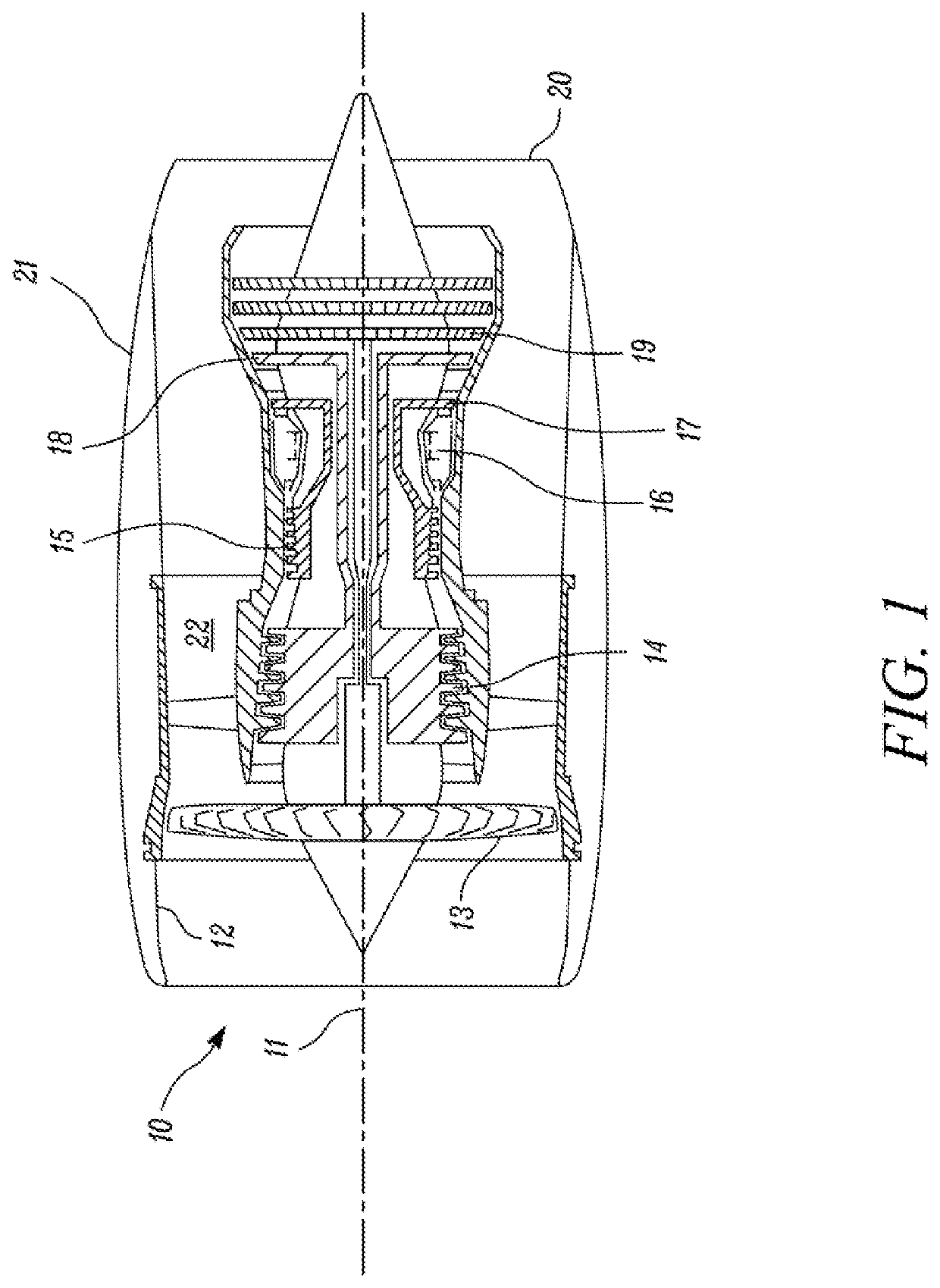
[0032]With reference to FIG. 1, an example of an aircraft engine, in this case a gas turbine engine, is generally indicated at 10, having a principal and rotational axis 11. The engine 10 comprises, in axial flow series, an air intake 12, a propulsive fan 13, an intermediate pressure compressor 14, a high-pressure compressor 15, combustion equipment 16, a high-pressure turbine 17, an intermediate pressure turbine 18, a low-pressure turbine19 and an exhaust nozzle 20. A nacelle 21 generally surrounds the engine 10 and defines both the intake 12 and the exhaust nozzle 20.

[0033]The aircraft engine 10 works in the conventional manner for a gas turbine engine so that air entering the intake 12 is accelerated by the fan 13 to produce two air flows: a first air flow into the intermediate pressu...


PUM


Abstract

An aircraft engine comprising a fan, the fan having a diameter D and including a plurality of fan blades, the fan blades having a sweep metric S, each fan blade having a leading edge, and a forward-most portion on the leading edge of each fan blade being in a first reference plane. The aircraft engine further comprises a nacelle, comprising an intake portion forward of the fan, a forward edge on the intake portion being in a second reference plane, wherein the intake portion has a length L measured along an axis of the aircraft engine between the first reference plane and the second reference plane, the aircraft engine having a cruise design point condition Mrel, wherein Mrel is between 0.4 and 0.93, and L/D is between 0.2 and 0.45.

Description

CROSS-REFERENCE TO RELATED APPLICATIONS[0001]This application is based upon and claims the benefit of priority from UK Patent Application Number GB2014015.8 filed on 7 Sep. 2020, the entire contents of which are incorporated herein by reference.BACKGROUNDTechnical Field[0002]The present disclosure concerns an aircraft engine, particularly an air engine with a short intake.Description of the Related Art[0003]It is desirable for aircraft engines to be as fuel-efficient as possible. To that end, a current trend in engine design is towards larger (i.e. increased diameter) fans operating at slower rotation speeds. In the case of gas turbine engines, increasing the fan diameter allows for a larger bypass ratio.[0004]Reducing, the fan rotation speed helps reduce losses resulting from shockwaves at the fan. Such shockwaves are chiefly an issue for high-speed fans, i.e. fans designed for air moving through the fan with a high relative Mach number (Mrel). To mitigate this effect, a sweep is i...

Claims


Application Information

Patent Timeline
Patent Type & Authority Applications(United States)
IPC IPC(8): F01D5/14B64D27/10B64D27/24
CPCF01D5/141B64D27/10F05D2240/30F05D2220/323B64D27/24F05D2220/36F02K3/075F02K3/06B64D33/02Y02T50/60
Inventor MOHANKUMAR, BENJAMINWILSON, MARK J.HALL, CESARE A.
Owner ROLLS ROYCE PLC
Why Eureka
Try Eureka