Electronic device

Pending Publication Date: 2022-03-10
CANON KK
View PDF4 Cites 0 Cited by
  • Summary
  • Abstract
  • Description
  • Claims
  • Application Information

AI Technical Summary

Benefits of technology

The invention allows users to easily create compositions that capture a stationary object in a desired position.

Problems solved by technology

However, when there is a difference between the movement speed of the object and a movement speed (a pan speed) of the camera by the user, the user ends up with an image in which not only the background but the object is also blurred.
However, conventional art including the techniques disclosed in Japanese Patent Application Laid-open No. 2016-220024 and Japanese Patent Application Laid-open No. 2001-235782 does not enable a user to readily create a composition that captures a stationary main object at a position desired by the user.

Method used


Image

  • Electronic device
  • Electronic device
  • Electronic device

Examples


first embodiment

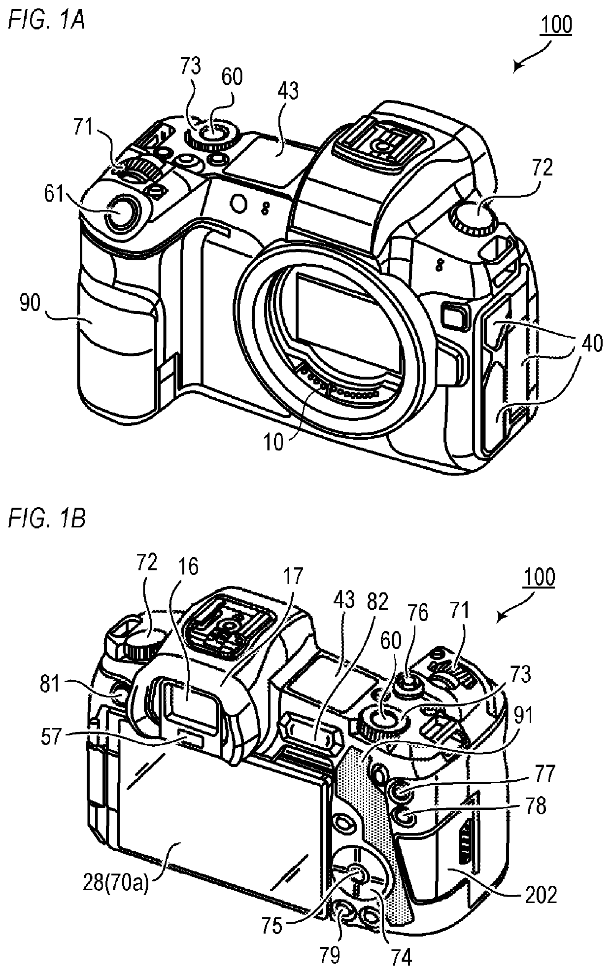
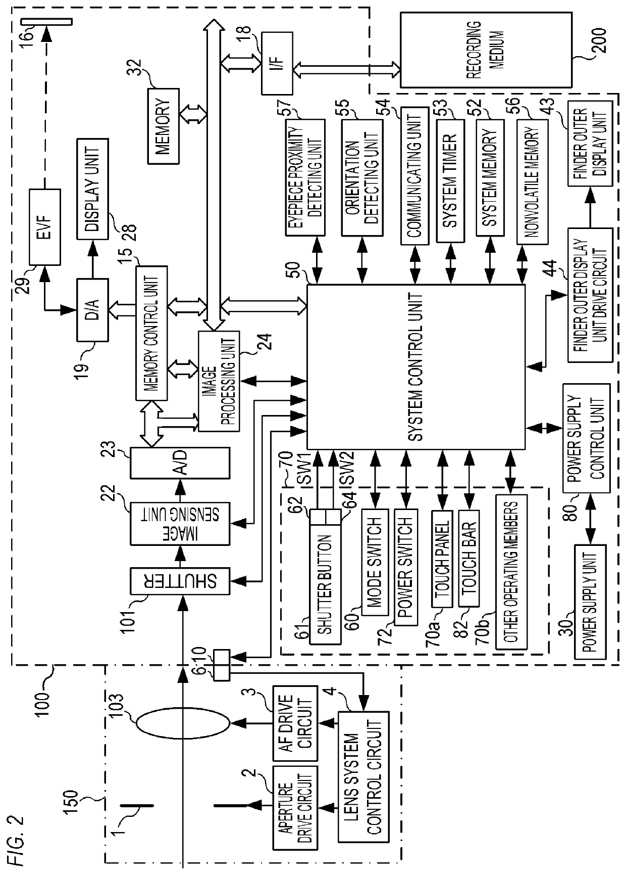
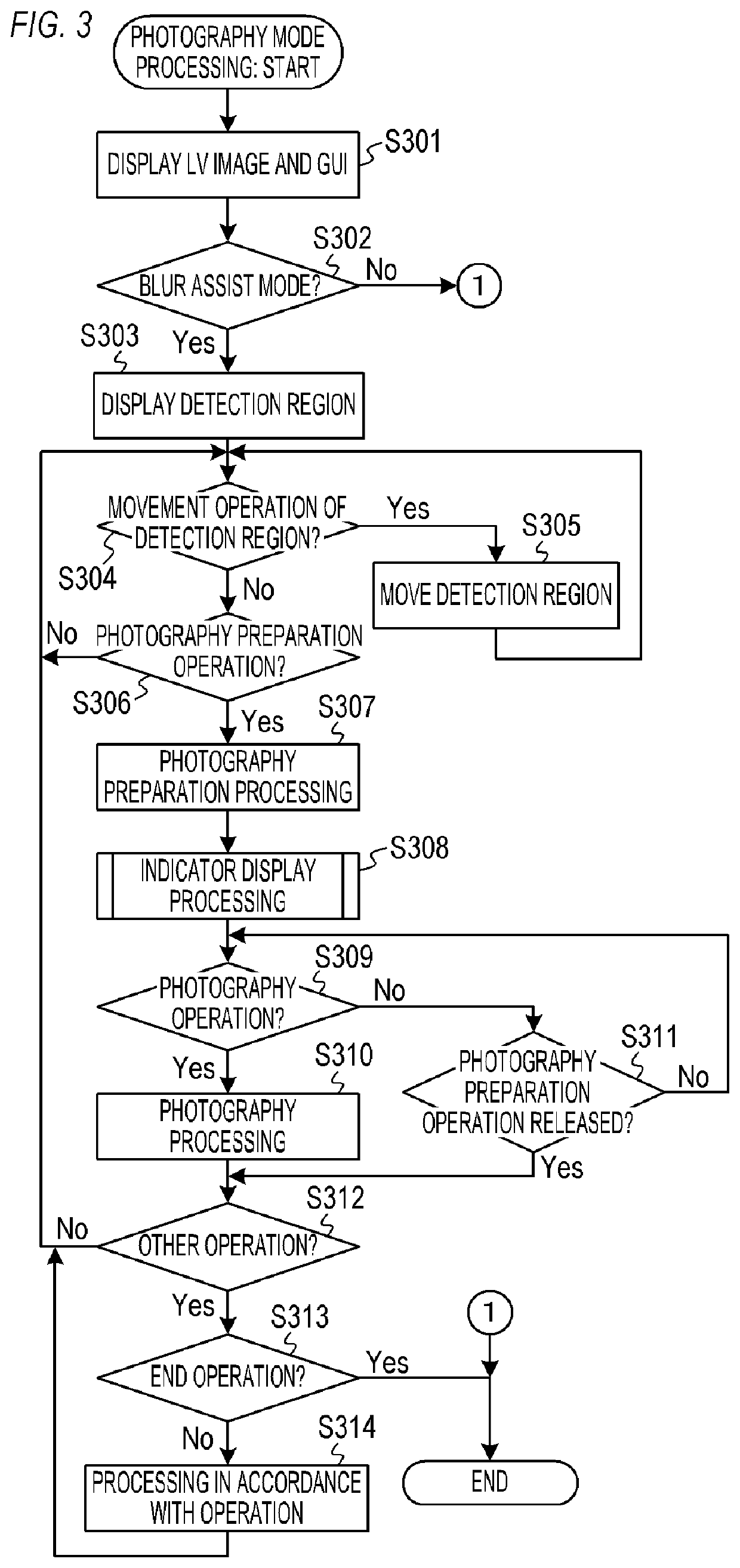
[0059]A first embodiment of the present invention will be described. FIG. 3 is a flow chart showing details of photography mode processing performed in the digital camera 100 according to the first embodiment. The processing is realized as the system control unit 50 deploys a program recorded in the nonvolatile memory 56 on the system memory 52 and executes the program. The processing shown in FIG. 3 is started when the digital camera 100 is activated in a photography mode or the system control unit 50 switches to the photography mode. The digital camera 100 repetitively performs the processing shown in FIG. 3 during the photography mode.

[0060]In S301, the system control unit 50 displays an LV image and a GUI such as an icon representing a setting state of the digital camera 100 on the display unit 28.

[0061]In S302, the system control unit 50 determines whether or not a blur assist mode is ON (enabled). When the blur assist mode is ON, the system control unit 50 advances to S303, bu...

second embodiment

[0109]A second embodiment of the present invention will be described. In the first embodiment, an example has been described in which the reference direction D is determined based on a motion vector detected from an LV image (a motion vector of a main object) and a movement direction detected using the orientation detecting unit 55 (a movement direction of the digital camera 100). In the second embodiment, an example in which the user designates a direction related to the reference direction D will be described. In addition, in the first embodiment, an example in which both a horizontal reference indicator and a vertical reference indicator are displayed has been described. In the second embodiment, an example in which only an indicator indicating a center of the detection region in a direction perpendicular to the reference direction D (an indicator on a straight line of the reference direction D that passes through the center of the detection region) among the horizontal reference...

third embodiment

[0145]A third embodiment of the present invention will be described. In the first embodiment, an example of determining the indicator distance L in accordance with a size of a main object present in a detection region has been described. In the third embodiment, an example in which the user designates the indicator distance L will be described.

[0146]As described in the first embodiment, an indicator is preferably displayed so as not to overlap with the main object. In consideration thereof, in the third embodiment, the indicator distance L is to be designated (set) by the user. Accordingly, a situation where an indicator overlaps with the main object can be more reliably suppressed and the display of the indicator can be adjusted to suit the user's preferences. The operation for designating the indicator distance L is performed using, for example, the four-way key 74, the touch panel 70a, or the SET button 75.

[0147]FIG. 8 is a flow chart showing details of setting processing for set...


PUM


Abstract

An electronic device according to the present invention, includes: a processor; and a memory storing a program which, when executed by the processor, causes the electronic device to: acquire an image by image sensing processing; set a part of the image as a specific region, wherein a position of the specific region can be changed; and detect a motion of an object included in the specific region; and perform control to display an indicator based on the detected motion of the object in a direction corresponding to a movement direction of the electronic device so that the indicator is superimposed and displayed at a position on the image based on the specific region.

Description

BACKGROUND OF THE INVENTIONField of the Invention[0001]The present invention relates to an electronic device and, particularly, to a technique for assisting panning.Description of the Related Art[0002]One photography method of an image (a still image) that expresses a sense of speed of a moving object is panning. In panning, photography is performed at a slower shutter speed than usual while following an object (a moving body) to obtain an image in which a background flows while the object is stationary (an image in which the background blurs but the object does not). For example, a user obtains an image such as that described above by performing photography while moving (panning) a camera in accordance with a motion of the object. In this case, the shutter speed is set slower than usual based on a movement speed of the object (an exposure time is adjusted to longer than usual based on the movement speed of the object). However, when there is a difference between the movement speed ...

Claims


Application Information

Patent Timeline
IPC IPC(8): H04N5/232
CPCH04N5/23254H04N5/23299G06T7/215H04N5/23222H04N5/232939H04N23/61H04N23/6811H04N23/6815H04N23/635H04N23/695H04N23/64H04N23/633H04N23/58
Inventor WATANABE, KAZUHIROKIKKAWA, TAKESHIKOBAYASHI, SATORUNAKAMURA, HIROSHISATO, AKIHIKONAKATA, TAKESHI
Owner CANON KK
Why Eureka
Try Eureka