Tool Adapter with a Slidable Collar and a Plurality of Socket Adapters

a tool adapter and socket technology, applied in the field of tool adapters, can solve the problems of affecting the ability of users and wanting the collar to adjust, and achieve the effect of speeding up the time it takes users to complete the job

Pending Publication Date: 2022-03-17
LAWRENCE GLADSTON
View PDF0 Cites 2 Cited by
  • Summary
  • Abstract
  • Description
  • Claims
  • Application Information

AI Technical Summary

Benefits of technology

[0008]It is therefore an object of the present invention to provide a collar that is slidable along an elongated shaft. In use, the collar will encase the adapter that is in an unusable position. To alternate the position of the adapters, the collar will slide along the elongated shaft. When the collar is slid along the elongated shaft, the spring will compress. When the spring is compressed, the user may alternate the specific adapter that they intend to use by manually rotating the connector. Then when the desired adapter is in the proper useable position, the user will release the collar and the spring will retract and move the collar over the unused adapter. The quick action and ease of use of the sliding collar will allow the user to quickly alternate between the desired adapter on a single tool. This will not only speed up the time it takes the user to complete the job, but also allows them to transport a single tool that is capable of performing more than one function.

Problems solved by technology

While the tool adapter is coupled to a power tool, the user will not want the collar to adjust while they attempting to use the adapter.
If the collar were to move during use of the tool adapter, then the specific adapter may have undesired movement that will disturb the user and interrupt their ability to timely complete the job.

Method used


Image

  • Tool Adapter with a Slidable Collar and a Plurality of Socket Adapters
  • Tool Adapter with a Slidable Collar and a Plurality of Socket Adapters
  • Tool Adapter with a Slidable Collar and a Plurality of Socket Adapters

Examples


Embodiment Construction

[0018]Reference is made herein to the attached drawings. Like reference numerals are used throughout the drawings to depict like or similar elements of the tool adapter. For the purposes of presenting a brief and clear description of the present invention, the preferred embodiment will be discussed is the tool adapter with a pivoting connector with a pair of socket adapters. The figures are intended for representative purposes only and should not be limiting in any respect.

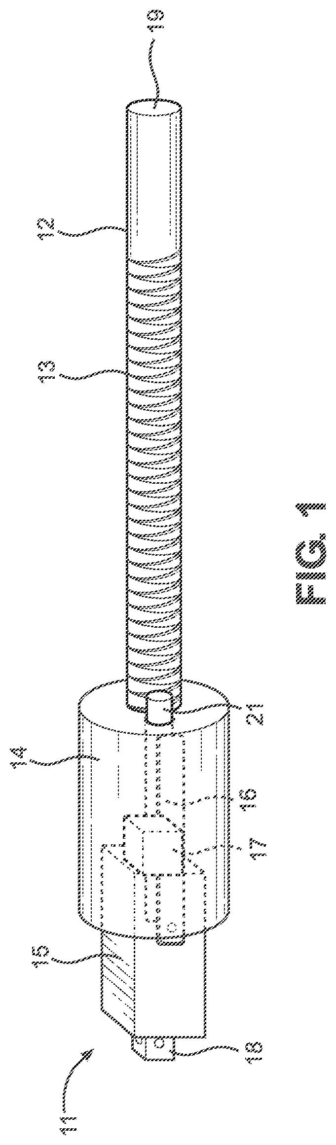
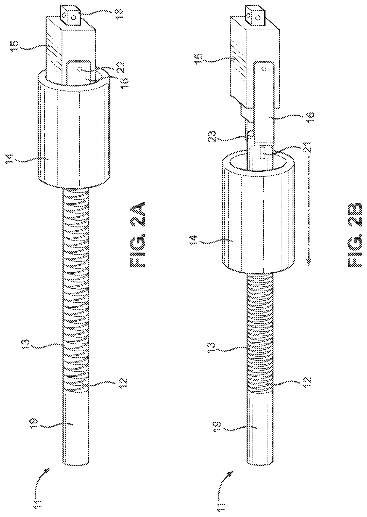
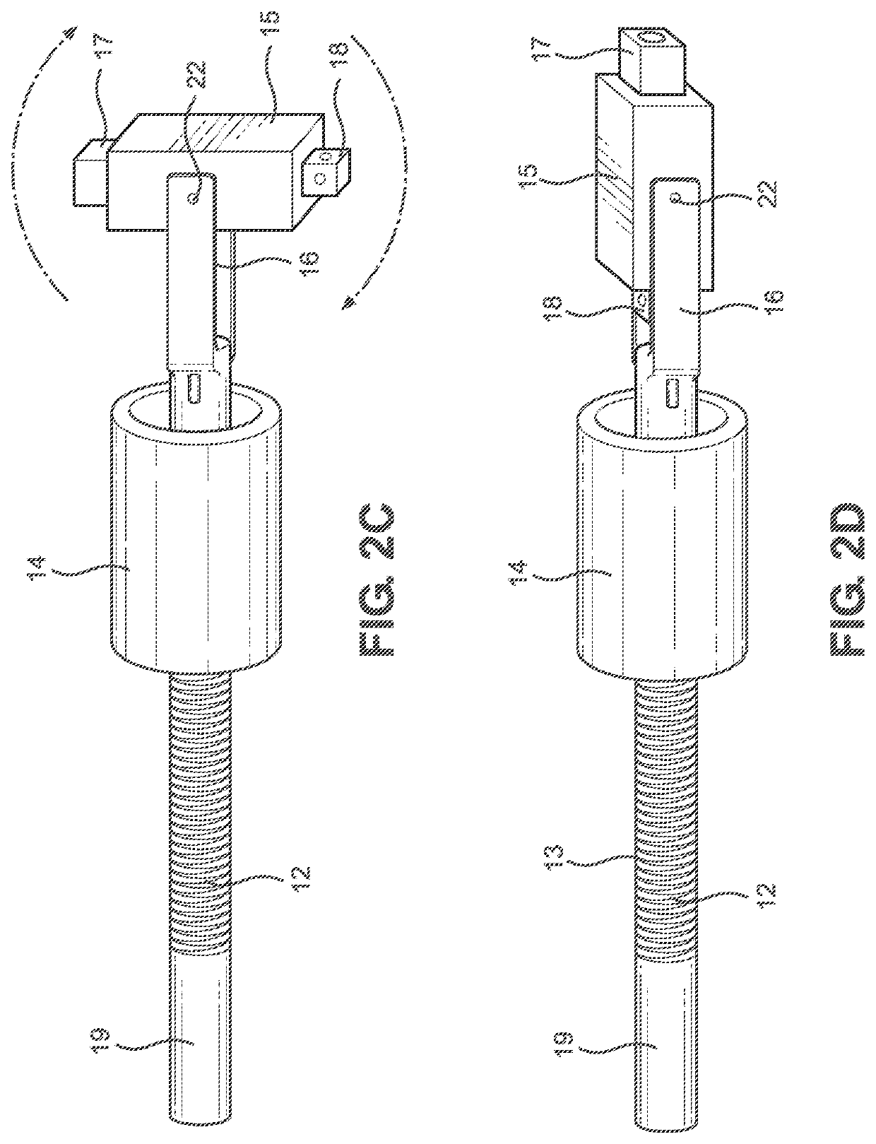
[0019]FIG. 1 shows a partial internal view of an embodiment of a tool adapter. The tool adapter 11 comprises an elongated shaft 12 and a collar 14. The elongated shaft 12 includes a working end and an attaching end 19. A spring 13 encases the elongated shaft 12. The collar 14 encircles the elongated shaft 12. The collar 14 is coupled with the spring 13. The spring 13 biases the collar 14 towards the working end of the elongated shaft 12. A pair of parallel arms 16 are disposed on opposing ends of the working end o...


PUM


Abstract

A tool adapter with a collar and a plurality of socket adapters is provided. The device includes an elongated shaft having an attaching end and a working end. A spring partially encircles the elongated shaft and is coupled to a collar. The spring biases the collar towards the working end of the elongated shaft. The collar is slidable along the elongated shaft. The collar partially encases a pivoting connector. The plurality of socket adapters is disposed on the pivoting connector. One or more removable locking pins secures the collar in position over the pivoting connector. A pair of parallel arms are disposed on opposing sides of the working end. The pivoting connector may freely rotate between a pair of parallel arms at a connecting point when the collar is slid towards the attaching end.

Description

CROSS REFERENCE TO RELATED APPLICATIONS[0001]This application claims the benefit of U.S. Provisional Application No. 63 / 079,515 filed on Sep. 17, 2020. The above identified patent application is herein incorporated by reference in its entirety to provide continuity of disclosure.BACKGROUND OF THE INVENTION[0002]The present invention relates to a tool adapter. More specifically, the present invention provides a tool adapter that includes a slidable collar that partially covers a pivoting connector with a pair of opposing socket adapters.[0003]Many individuals utilize power tools to aid in the completion of construction projects. Unfortunately, a drawback to such power tools is that many are only capable of performing a single task. The power tools lack the ability to be adjusted to fit types of sockets or other tools. Tools that only possess a singular purpose are also present in more general tools, such as wrenches and other manually operated drivers. For example, most socket wrench...

Claims


Application Information

Patent Timeline
Patent Type & Authority Applications(United States)
IPC IPC(8): B25B21/00B25B23/00
CPCB25B21/007B25B23/0035
Inventor LAWRENCE, GLADSTON
Owner LAWRENCE GLADSTON
Why Eureka
Try Eureka