Work machine and method for controlling work machine

Pending Publication Date: 2022-03-24
KOMATSU LTD
View PDF4 Cites 0 Cited by
  • Summary
  • Abstract
  • Description
  • Claims
  • Application Information

AI Technical Summary

Benefits of technology

[0012]In the present disclosure, the target tractive force is corrected so as to be equal to or less than the upper limit when the target tractive force is greater than the upper limit. As a result, torque for the apparatus drive system can be assured in comparison to when the output of the engine is limited. As a result, a reduction in workability can be suppressed. M

Problems solved by technology

However, in this case, the desired required torque of the work implement cannot be obtained and there is a concern that workability is decreased.
However, the work machine is not limited to traveling on flat roads and may be traveling on rough roads or on steep slop

Method used


Image

  • Work machine and method for controlling work machine
  • Work machine and method for controlling work machine
  • Work machine and method for controlling work machine

Examples


Example

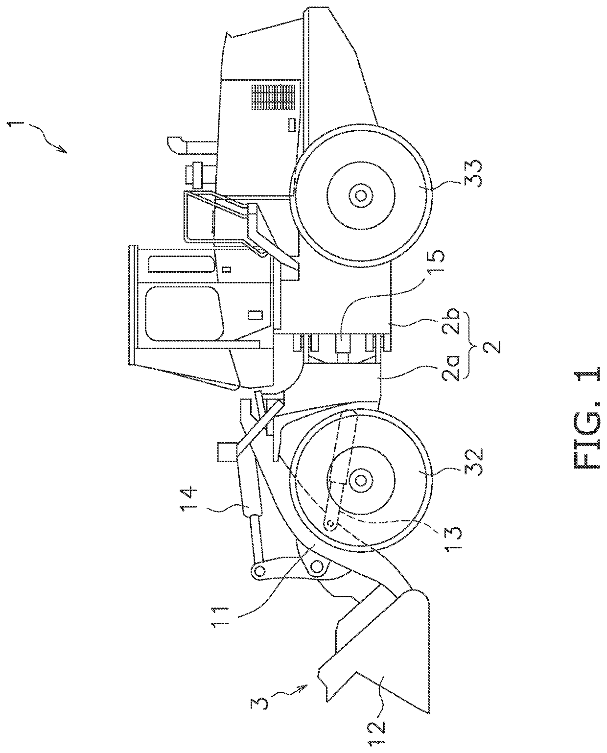
[0022]Embodiments of the present invention will be explained in detail with reference to the figures. FIG. 1 is a side view of a work machine 1 according to an embodiment of the present invention. As illustrated in FIG. 1, the work machine 1 includes a vehicle body 2 and a work implement 3.

[0023]The vehicle body 2 includes a front vehicle body 2a and a rear vehicle body 2b. The rear vehicle body 2b is connected to the front vehicle body 2a so as to allow turning to the left and right. The front vehicle body 2a and the rear vehicle body 2b are coupled by a hydraulic cylinder 15. The hydraulic cylinder 15 extends and contracts whereby the front vehicle body 2a turns to the left or right with respect to the rear vehicle body 2b.

[0024]The work implement 3 is used for work such as excavation. The work implement 3 is attached to the front vehicle body 2a. The work implement 3 includes a boom 11, a bucket 12, and hydraulic cylinders 13 and 14. The hydraulic cylinders 13 and 14 extend and ...


PUM


Abstract

A work machine includes an engine, a travel drive system, a work implement, an apparatus drive system with a hydraulic pump, an accelerator operating member, a work implement operating member, and a controller. The controller controls the apparatus drive system in accordance with an operating amount of the work implement operating member. The controller determines a target tractive force of the travel drive system based on an operating amount of the accelerator operating member. The controller determines an allowable acceleration of the work machine. The controller determines an upper limit of tractive force of the travel drive system based on the allowable acceleration. The controller corrects the target tractive force so as to be equal to or less than the upper limit when the target tractive force is greater than the upper limit. The controller controls the travel drive system based on the corrected target tractive force.

Description

[0001]This application is a U.S. National stage application of International Application No. PCT / JP2020 / 009838, filed on Mar. 6, 2020. This U.S. National stage application claims priority under 35 U.S.C. § 119(a) to Japanese Patent Application No. 2019-062992, filed in Japan on Mar. 28, 2019, the entire contents of which are hereby incorporated herein by reference.BACKGROUNDField of the Invention[0002]The present invention relates to a work machine and a method for controlling a work machine.Background Information[0003]In International Publication WO 2014 / 208614, a technique is disclosed in which a controller in a work machine determines a target tractive force of a transmission based on an operation of an accelerator operating member. As a result, the operator is able to optionally operate torque for causing the work machine to travel with the accelerator operating member.[0004]In addition, the controller in International Publication WO 2014 / 208614 determines a required torque of a...

Claims


Application Information

Patent Timeline
IPC IPC(8): E02F9/22E02F9/20B60W30/188B60W10/06B60W10/10
CPCE02F9/2253E02F9/2066E02F9/2079E02F3/283B60W10/06B60W10/10E02F9/2246B60W30/188B60W10/04B60W10/103B60W2300/17B60W2540/10B60W2710/0666B60W2710/105
Inventor TAKENAKA, YUITAYAMADA, KENICHI
Owner KOMATSU LTD
Why Eureka
Try Eureka