
Method for manufacturing elastic body having two-layer structure, cylinder member, and image forming apparatus

Pending Publication Date: 2022-03-31
FUJIFILM BUSINESS INNOVATION CORP
View PDF3 Cites 0 Cited by
  • Summary
  • Abstract
  • Description
  • Claims
  • Application Information

AI Technical Summary

Benefits of technology

The present patent relates to a method for making an elastic body with two layers. The method involves making two layers of elastic on a circular cylinder and then forming a second layer that is integrated with the first layer. The technical effect of this method is that it prevents the two layers from peeling off when the elastic body is wound on a cylinder. This is beneficial because it improves the quality and durability of the elastic body.

Problems solved by technology

However, aspects of the non-limiting embodiments are not required to address the advantages described above, and aspects of the non-limiting embodiments of the present disclosure may not address advantages described above.

Method used


Image

  • Method for manufacturing elastic body having two-layer structure, cylinder member, and image forming apparatus
  • Method for manufacturing elastic body having two-layer structure, cylinder member, and image forming apparatus
  • Method for manufacturing elastic body having two-layer structure, cylinder member, and image forming apparatus

Examples


Embodiment Construction

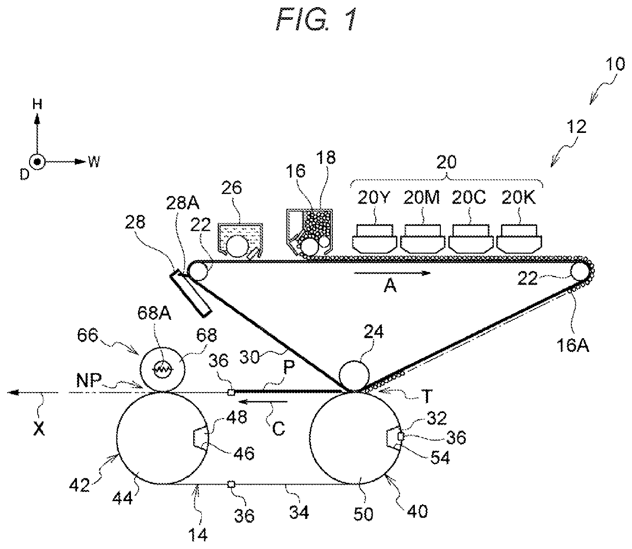
[0018]Hereinafter, an exemplary embodiment of the present disclosure will be described in detail with reference to the accompanying drawings. For the convenience of description, a direction along an arrow H illustrated in FIG. 1 will be referred to as an up and down direction of an image forming apparatus 10, a direction along an arrow W will be referred to as a width direction of the image forming apparatus 10, and a direction along an arrow D will be referred to as a front to rear direction (or a depth direction) of the image forming apparatus 10.

[0019]As illustrated in FIG. 1, the image forming apparatus 10 is, for example, an inkjet apparatus that forms an ink image (an example of an image) on a recording medium P. The image forming apparatus 10 includes an image forming unit 12, a transport unit 14, and a fixing device 66 in an apparatus body (not illustrated).

[0020]Hereinafter, the respective units of the image forming apparatus 10 (that is, the image forming unit 12, the tran...


PUM


Abstract

A method for manufacturing an elastic body having a two-layer structure includes: forming a first elastic body on a provisional cylinder body having a substantially circular shape in cross section; and forming a second elastic body integrally with the first elastic body, which has been formed on the provisional cylinder body.

Description

CROSS-REFERENCE TO RELATED APPLICATIONS[0001]This application is based on and claims priority under 35 USC 119 from Japanese Patent Application No. 2020-166252 filed Sep. 30, 2020.BACKGROUND(i) Technical Field[0002]The present disclosure relates to a method for manufacturing an elastic body having a two-layer structure, a cylinder member, and an image forming apparatus.(ii) Related Art[0003]The following transfer device has been known. That is, the transfer device includes a transport unit and a gripper piece. The transport unit moves a transfer material along a circulation movement path. The gripper piece is attached to the transport unit. The gripper piece is supported by a rotation shaft so as to rotate with respect to a base member and to grip a leading side of the transfer material. The transfer device transfers an image on an image carrier onto the transfer material (for example, see JP-A-58-005769).SUMMARY[0004]Aspects of non-limiting embodiments of the present disclosure rel...

Claims


Application Information

Patent Timeline
IPC IPC(8): B41J15/04G03G15/00B65H5/06
CPCB41J15/046B65H5/062G03G15/6529G03G15/652G03G15/2053G03G15/1685B41J11/007B65H2404/1119B65H2404/18B65H2801/06
Inventor BABA, TOSHIAKIYOSHIOKA, TOMOAKIMIYAMOTO, YOKOKISHI, KAZUKITSUTSUMI, YOSUKE
Owner FUJIFILM BUSINESS INNOVATION CORP
Features
  • Generate Ideas
  • Intellectual Property
  • Life Sciences
  • Materials
  • Tech Scout
  • Unparalleled Data Quality
  • Higher Quality Content
  • 60% Fewer Hallucinations
Learn More