Bearing device for radial piston machine

Pending Publication Date: 2022-03-31
DAIDO METAL CO LTD
View PDF0 Cites 0 Cited by
  • Summary
  • Abstract
  • Description
  • Claims
  • Application Information

AI Technical Summary

Benefits of technology

The present invention provides a bearing device for a radial piston machine that prevents damage caused by friction between the outer surface of the half-bearing and the piston, or deformation of the half-bearing.

Problems solved by technology

In the case of the conventional bearing devices (JP 2008-196410 A, JP 2012-122498 A, JP 2009-531596 A, JP S62-058064 A) in which both circumferential end faces of the half bearing are constrained by a constraining means such as the step surface of the piston, slight sliding occurs between an outer circumferential surface (surface of the back metal layer made of an Fe alloy) of the half bearing and a bearing holding surface of the piston during operation, and therefore fretting damage tends to be caused on the outer circumferential surface of the half bearing.
Therefore, the surfaces of the projecting portions strongly contact with the surface of the roller, and damage tends to be caused.

Method used


Image

  • Bearing device for radial piston machine
  • Bearing device for radial piston machine
  • Bearing device for radial piston machine

Examples


embodiment 1

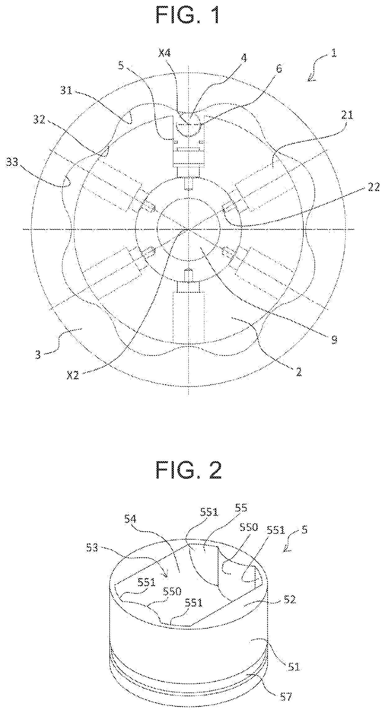
[0043]FIG. 1 illustrates a hydraulic radial piston motor as one example of a bearing device 1 for a radial piston machine. The bearing device 1 of the hydraulic radial piston motor has a cam ring 3 in which an approximately waveform cam face 31 is formed on an inner circumference, a rotor (cylinder block) 2 is arranged in the cam ring 3, and an output shaft 9 is further coupled to the rotor 2.

[0044]The cam face 31 of the cam ring 3 has eight cam lobes 32 arranged circumferentially at equal intervals (equal pitch) as illustrated in FIG. 1.

[0045]The rotor 2 has six cylinders 21 arranged circumferentially at equal intervals (equal pitch) as illustrated in FIG. 1, each extending radially, and having the same diameter. Each cylinder 21 communicates with a cylinder port 22.

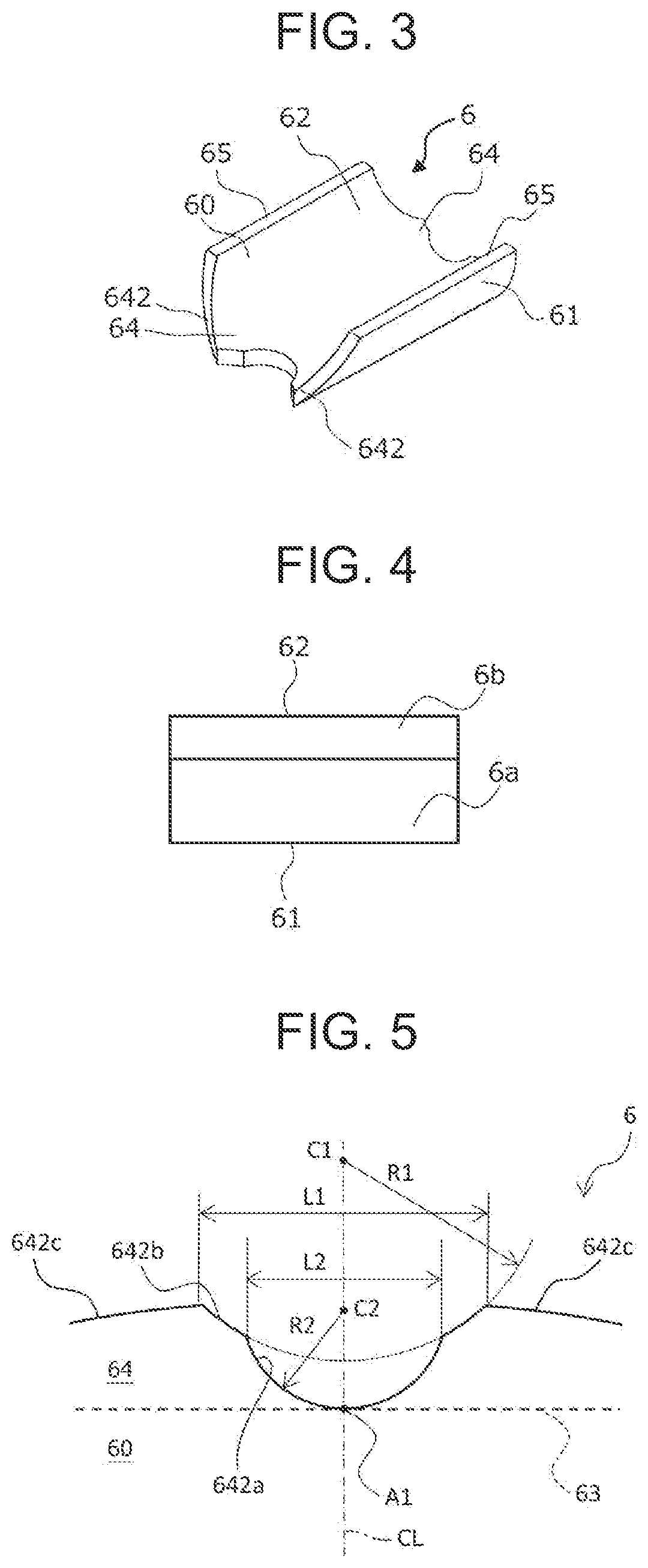
[0046]One piston 5 is fitted into each of the six cylinders 21 so as to be able to reciprocate therein, and the piston 5 holds, via a half bearing 6, a roller 4 which rolls on the cam face 31 of the cam ring 3. The roll...

embodiment 2

[0081]A half bearing 6 having a protruding portion 64 different from that according to Embodiment 1 is described below by use of FIG. 11. It should be noted that the same reference signs are assigned to components that are identical with or equivalent to those in the contents described in Embodiment 1.

(Configuration)

[0082]The overall configuration of a bearing device 1 according to the present embodiment is similar to that according to Embodiment 1. The configuration of the half bearing 6 is also approximately similar to that according to Embodiment 1 except for the shape of the protruding portion 64.

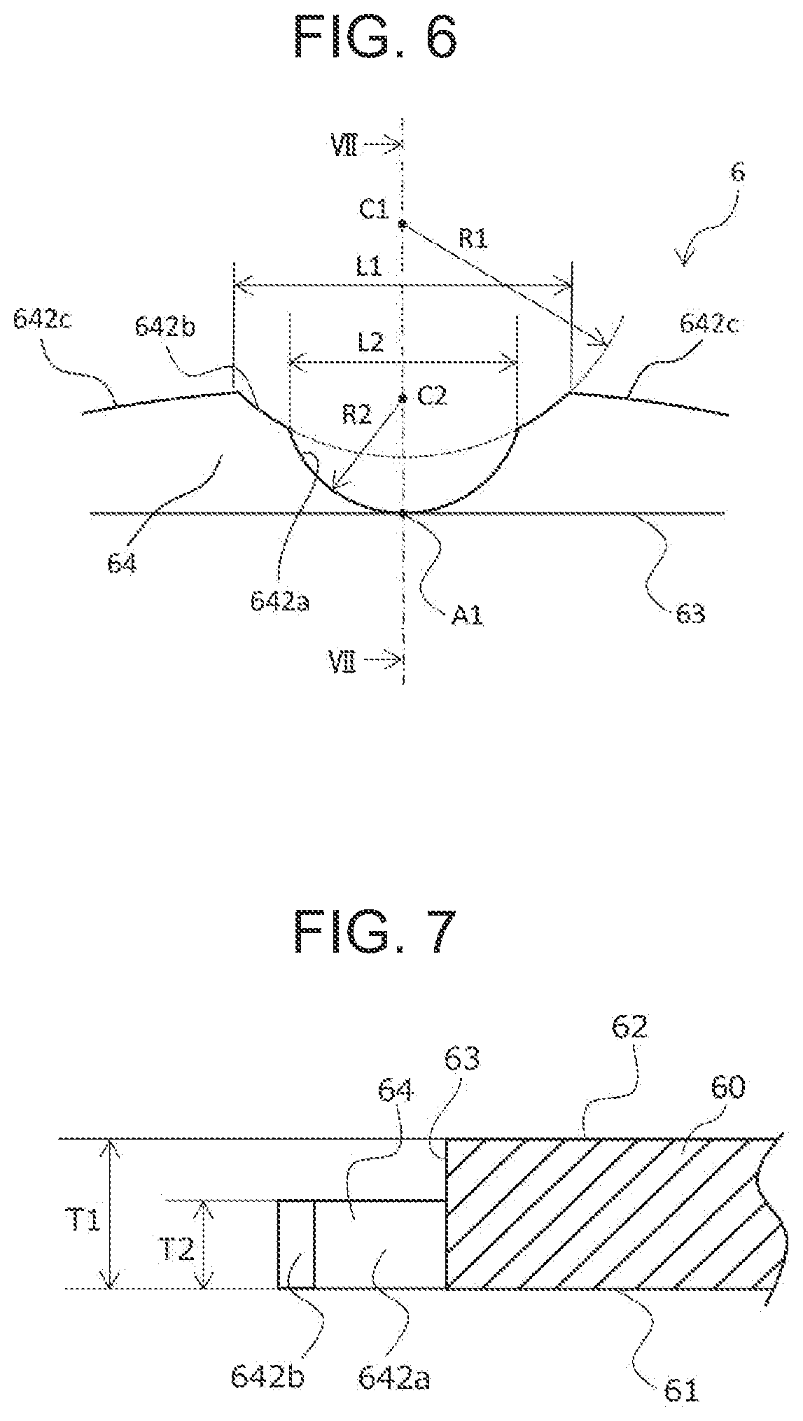
[0083]A protruding portion end face 642 facing toward the axially outer side of the protruding portion 64 of the half bearing 6 according to Embodiment 2 further includes, in addition to the central recessed surface 642a and the support recessed portions 642b, parallel surfaces 642d, 642d extending parallel to the circumferential direction of the half bearing 6, between the two support ...


PUM


Abstract

A bearing device includes a piston arranged in a cylinder of a rotor, and a half bearing mounted on the piston to support a roller. The piston includes a recessed holding surface, and holding side surfaces on both axial sides thereof. Each holding side surface includes a ridge portion having an arc-shaped or elliptic-arc-shaped profile protruding toward a radially inner side of the piston. The half bearing includes a partially cylindrical portion, and protruding portions protruding from axial end faces thereof. Each protruding portion has a protruding portion end face which includes a central recessed surface, and two support recessed surfaces located on both circumferential sides thereof, that have an arc shape or an elliptic arc shape to correspond to the profile of the ridge portion, so that only the two support recessed surfaces are in contact with the ridge portion.

Description

BACKGROUND OF THE INVENTION(1) Field of the Invention[0001]The present invention relates to a bearing device for a radial piston machine such as a radial piston motor or a radial piston pump.(2) Description of Related Art[0002]As a conventional radial piston machine, a hydraulic radial piston motor described in JP 2008-196410 A is known. This hydraulic radial piston motor includes a cam ring having an approximately waveform cam face on its inner circumference, in which cam ring a rotor (cylinder block) is arranged, and an output shaft is coupled to the rotor. A plurality of radially extending cylinders are arranged in line in a circumferential direction in the rotor, and each of the cylinders has a cylinder port with which the cylinder communicates. One piston is arranged in each of the cylinders so as to be able to reciprocate therein, and the piston holds a roller which rolls on the cam face of the cam ring. The roller has a cylindrical shape, and is supported by a semi-cylindrica...

Claims


Application Information

Patent Timeline
IPC IPC(8): F01B13/06F01B1/06F02B57/10
CPCF01B13/061F02B57/10F01B1/0651F01B1/0644F02B75/222F02B75/32
Inventor IMAMURA, AKIYOSHISUZUKI, YUOGURI, MARINA
Owner DAIDO METAL CO LTD
Why Eureka
Try Eureka