Adjustible center post for multi-door enclosures

a center post and enclosure technology, applied in the field of center posts, can solve the problems of laborious and difficult techniques for mounting these posts in the door opening during cabinet assembly, and achieve the effects of reducing sagging of the roof panel, increasing the length of the post assembly, and removing sagging

Active Publication Date: 2022-04-07
S&C ELECTRIC
View PDF6 Cites 1 Cited by
  • Summary
  • Abstract
  • Description
  • Claims
  • Application Information

AI Technical Summary

Benefits of technology

[0004]The following discussion discloses and describes an adjustable center post assembly for eliminating sagging of a roof panel in a cabinet, where the center post assembly is positioned at or near a center of a door opening in the cabinet, and where doors of the cabinet latch to the post assembly. The post assembly includes a base portion and a post portion, where one of the base portion or the post portion includes a plurality of slots and the other one of the base portion or the slot portion includes a plurality of threaded studs. The base portion further includes a first bracket and a jackscrew threaded into a threaded opening in the first bracket and the post portion further includes a second bracket, where the jackscrew engages the second bracket so that rotation of the jackscrew causes the second bracket to move relative to the first bracket so that the studs slide in the slots and increase the length of the post assembly to remove the sag.

Problems solved by technology

However, the techniques for mounting these posts in the door opening during cabinet assembly can often be challenging because the top part of the door opening that is sagging needs to be lifted so that the post is able to fit therein.
However, because of the size and weight of the cabinet, these processes require significant force, and often more than one person, thus making them labor intensive.

Method used


Image

  • Adjustible center post for multi-door enclosures
  • Adjustible center post for multi-door enclosures

Examples


Embodiment Construction

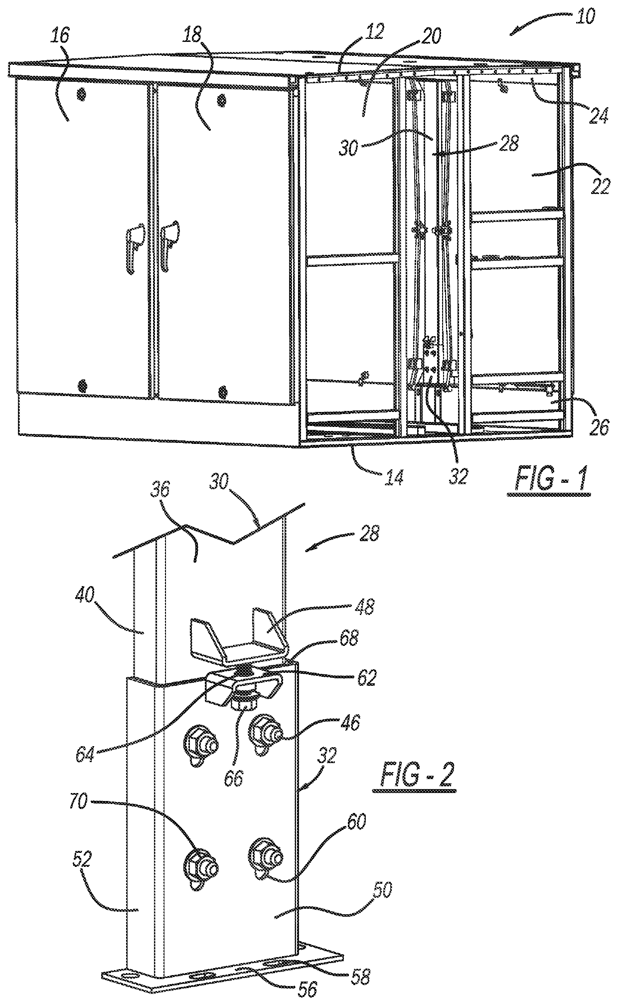
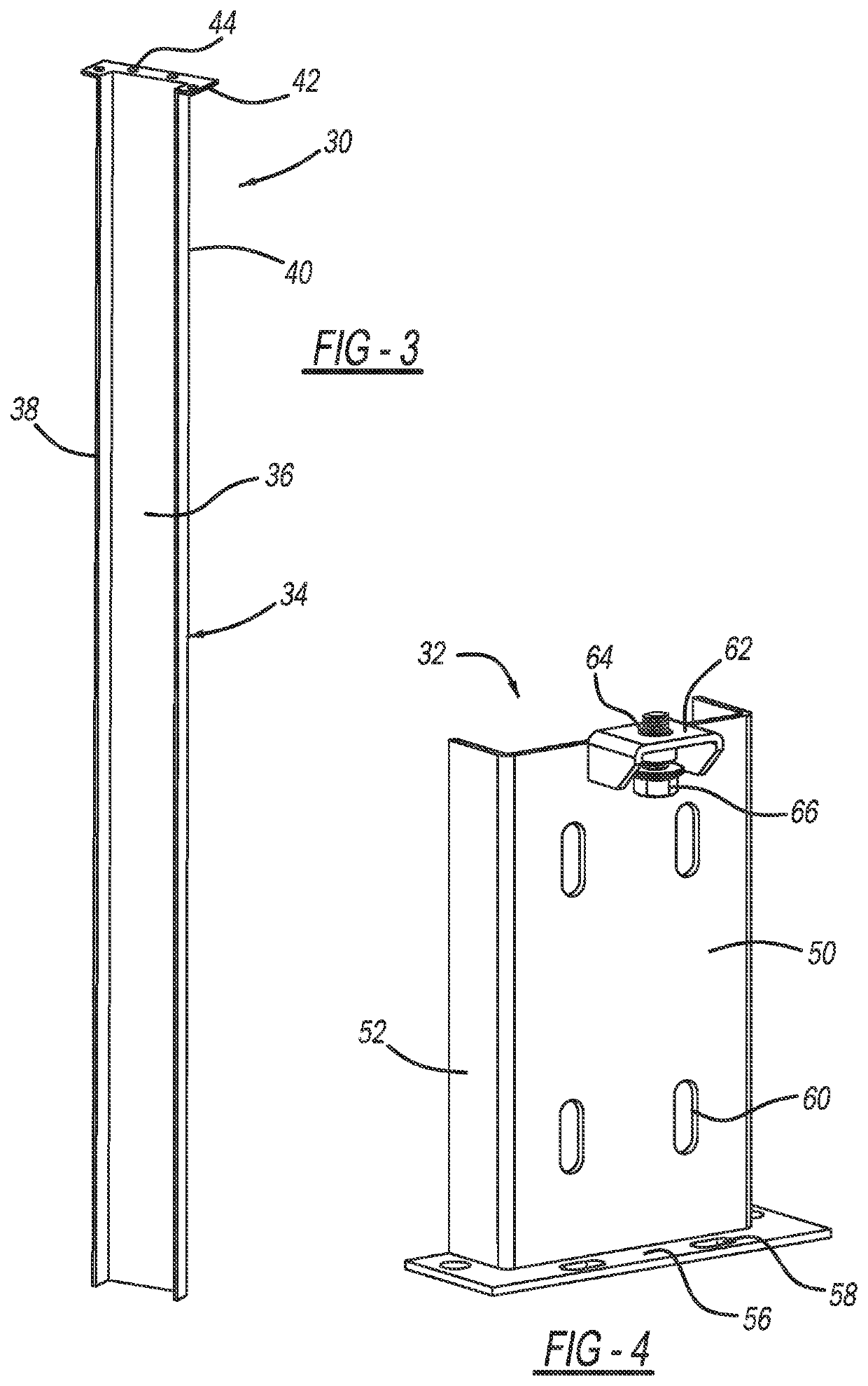
[0010]The following discussion of the embodiments of the disclosure directed to an adjustable center post assembly for supporting a top panel of a cabinet that encloses electrical equipment, where the post assembly includes a base portion and a post portion slidably inserted into the base portion, is merely exemplary in nature, and is in no way intended to limit the disclosure or its applications or uses. For example, the center post assembly is described herein as being applicable for cabinets that house electrical equipment. However, as will be appreciated by those skilled in the art, the post assembly may have application for other types of cabinets.

[0011]FIG. 1 is an isometric view of a cabinet 10 that is configured to house and hold electrical equipment of various types, none of which is shown, where a side panel of the cabinet 10 has been removed to expose the interior of the cabinet 10. The cabinet 10 includes a top panel 12, a bottom panel 14, a pair of opposing doors 16 and...


PUM


Abstract

A center post assembly for eliminating sagging of a roof panel in a cabinet, where doors of the cabinet latch to the post assembly. The post assembly includes a base portion and a post portion, where one of the base portion or the post portion includes a plurality of slots and the other one of the base portion or the slot portion includes a plurality of threaded studs. The base portion further includes a first bracket and a jackscrew threaded into a threaded opening in the first bracket and the post portion further includes a second bracket, where the jackscrew engages the second bracket so that rotation of the jackscrew causes the second bracket to move relative to the first bracket so that the studs slide in the slots and increase the length of the post assembly to remove the sag.

Description

CROSS-REFERENCE TO RELATED APPLICATION[0001]This application claims the benefit of priority from the U.S. Provisional Application No. 63 / 086,213, filed on Oct. 1, 2020, the disclosure of which is hereby expressly incorporated herein by reference for all purposes.BACKGROUNDField[0002]This disclosure relates generally to a center post for supporting a top panel of a cabinet and, more particularly, to an adjustable center post assembly for supporting and eliminating sag of a top panel of a cabinet, where double doors of the cabinet are latched to the center post assembly, and where the center post assembly includes a base portion and a post portion slidably inserted into the base portion to provide an adjustable height.Discussion of the Related Art[0003]An electrical power distribution system, often referred to as an electrical grid, typically includes a vast network of power lines for delivering power to a number of loads, such as homes, businesses, etc. These power distribution syste...

Claims


Application Information

Patent Timeline
Patent Type & Authority Applications(United States)
IPC IPC(8): A47B96/14
CPCA47B96/1425H02B1/30H02B1/303H02B1/012A47B45/00A47B2220/0002
Inventor DYER, THOMAS J.MILTON, JOSEPH W.
Owner S&C ELECTRIC
Why Eureka
Try Eureka