Beam report for multi-stream communication

a beam-based communication and beam-based technology, applied in the field of wireless communication networks, can solve problems such as destructive interference and constructive interference of others

Active Publication Date: 2022-04-14
QUALCOMM INC
View PDF0 Cites 2 Cited by
  • Summary
  • Abstract
  • Description
  • Claims
  • Application Information

AI Technical Summary

Benefits of technology

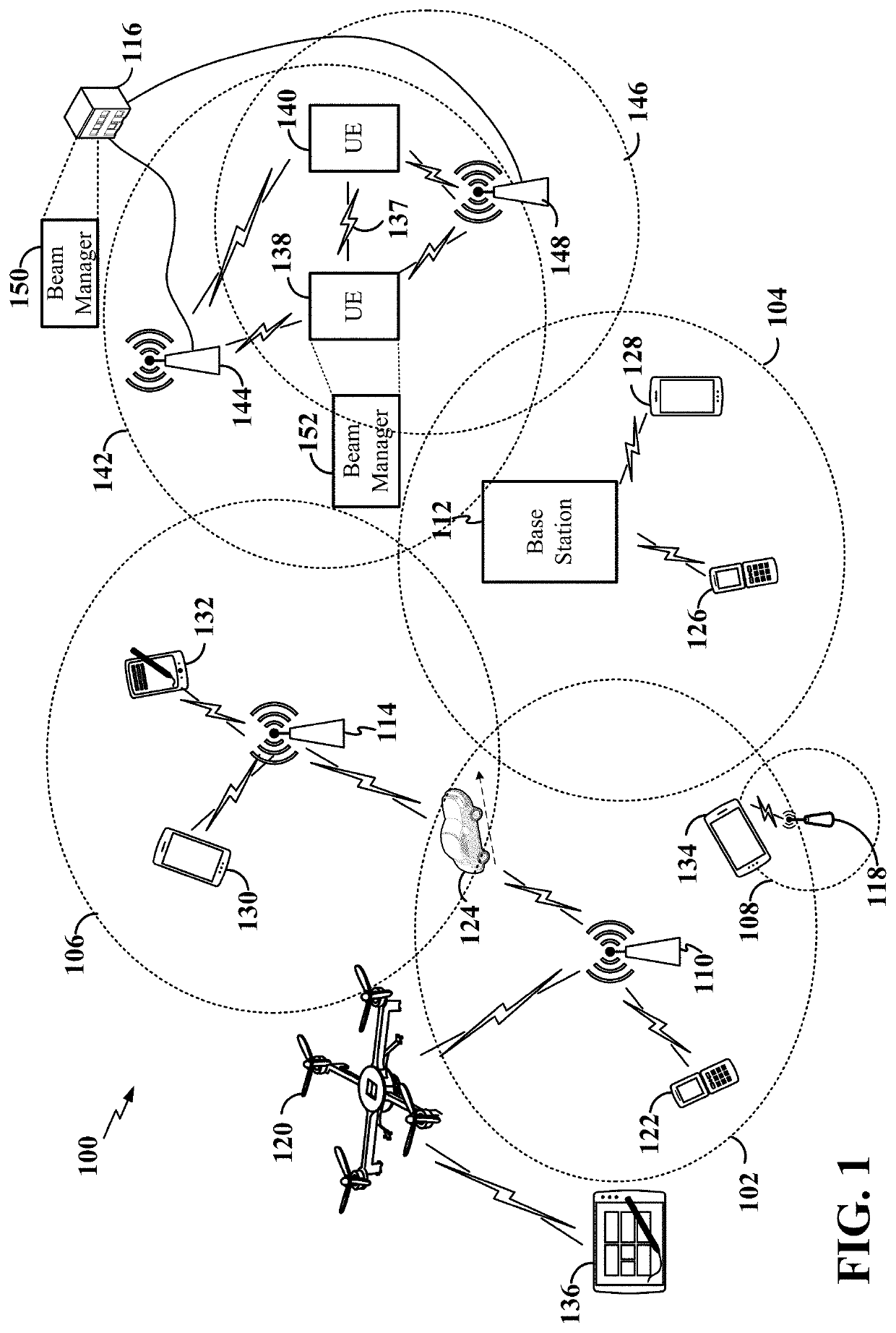
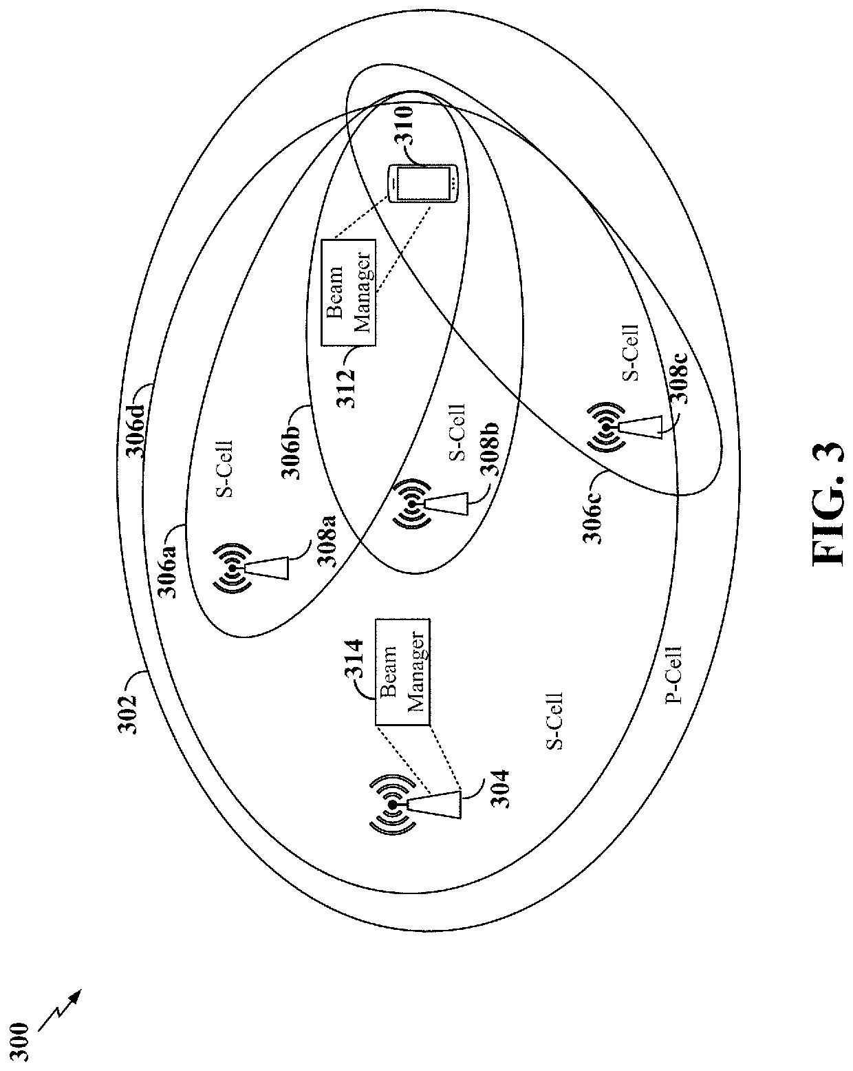
[0004]To increase the data rate on the downlink, multiple BPLs can be used to facilitate spatial multiplexing of multiple data streams from the base station to the UE. At the UE, the different BPLs can include receive beams from the same antenna panel or different antenna panels. At the base station, the different BPLs can include transmit beams from different transmission and reception points (TRPs), which may be collocated or non-collocated.BRIEF SUMMARY

Problems solved by technology

Each antenna in the antenna array transmits a signal that is combined with other signals of other antennas of the same array in such a way that signals at particular angles experience constructive interference while others experience destructive interference.

Method used


Image

  • Beam report for multi-stream communication
  • Beam report for multi-stream communication
  • Beam report for multi-stream communication

Examples


example 2

[0179] The method of example 1, wherein the beam quality metric comprises at least one of a reference signal received power (RSRP), signal-to-interference-plus-noise ratio (SINK), or delay spread.

[0180]Example 3: The method of example 1 or 2, wherein the beam quality metric comprises the RSRP and each of the respective beam quality metric vectors comprises an RSRP vector.

[0181]Example 4: The method of any of examples 1 through 3, wherein the RSRP vectors for each of the plurality of transmit beams indicate a respective mutual interference between each of the plurality of transmit beams.

[0182]Example 5: The method of any of examples 1 through 4, wherein the beam report comprises a respective first beam quality metric vector for each of the plurality of transmit beams and a respective second beam quality metric vector for each of the plurality of transmit beams, the first beam quality metric vector comprises an RSRP vector and the second beam quality metric vector comprises one of an ...

example 8

[0185] The method of any of examples 1 through 7, wherein the receiving the plurality of transmit beams further comprises: receiving the plurality of transmit beams during a beam refinement procedure.

example 9

[0186] The method of any of examples 1 through 8, wherein each of the plurality of receive beams is associated with a respective one of a plurality of antenna panels on the UE.

[0187]Example 10: The method of any of examples 1 through 9, further comprising:

[0188]receiving at least two streams from different respective TRPs of the plurality of TRPs using at least two corresponding beam pair links, each comprising a respective transmit beam of the plurality of transmit beams and a respective receive beam of the plurality of receive beams, selected based on the beam report for spatial division multiplexing of the at least two streams.


PUM


Abstract

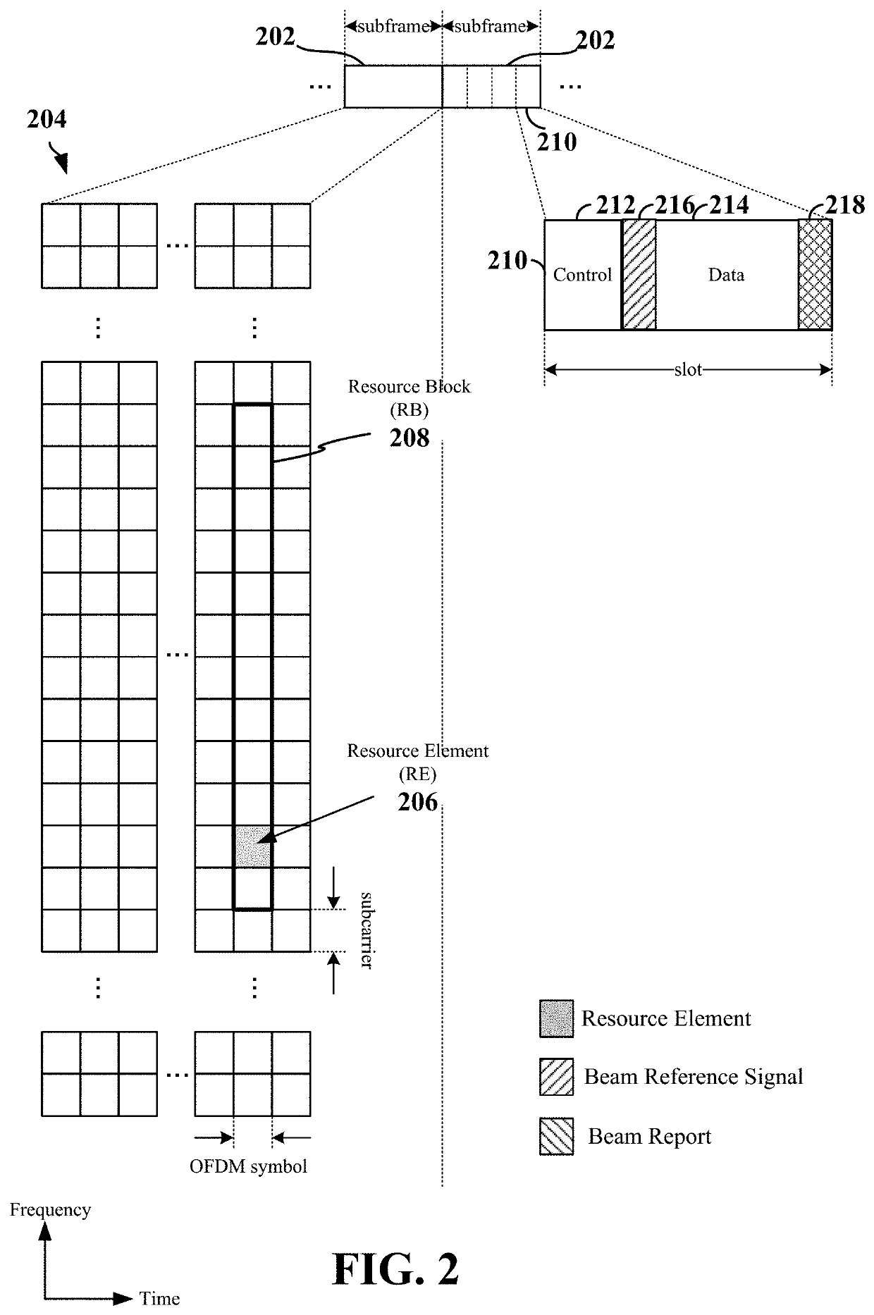
Aspects relate to beam management in multi-stream communication between a radio access network (RAN) entity and a user equipment (UE). The RAN entity may transmit a plurality of transmit beams from a plurality of transmission and reception points (TRPs) associated with the RAN entity to the UE. For each of the transmit beams, the UE may obtain a beam quality metric on each of a plurality of receive beams of the UE during a measurement period (e.g., in parallel or serially) to generate a respective beam quality metric vector for each of the transmit beams. The UE can then transmit a beam report including the respective beam quality metric vector for each of the transmit beams to the RAN entity. The RAN entity may then select at least two beam pair links, each associated with a respective TRP, for spatial division multiplexing of at least two streams to the UE based on the beam report.

Description

INTRODUCTION[0001]The technology discussed below relates generally to wireless communication networks, and more particularly, to beam measurement reporting in beam-based communication scenarios.[0002]In wireless communication systems, such as those specified under standards for 5G New Radio (NR), a base station and user equipment (UE) may utilize beamforming to compensate for high path loss and short range. Beamforming is a signal processing technique used with an antenna array for directional signal transmission and / or reception. Each antenna in the antenna array transmits a signal that is combined with other signals of other antennas of the same array in such a way that signals at particular angles experience constructive interference while others experience destructive interference.[0003]The base station and the UE can select one or more beam pair links (BPLs) for communication therebetween on the downlink and / or the uplink. Each BPL includes corresponding transmit and receive be...

Claims


Application Information

Patent Timeline
Patent Type & Authority Applications(United States)
IPC IPC(8): H04W24/08H04B17/318H04B17/336H04B7/06
CPCH04W24/08H04B7/0617H04B17/336H04B17/318H04B7/0695H04B7/088H04B7/024H04B7/0697H04B7/0417H04W72/0453H04W24/10
Inventor DALLAL, YEHONATANBERLINER, RANLANDIS, SHAY
Owner QUALCOMM INC
Why Eureka
Try Eureka