Measurement arrangement and method of monitoring rotation speed of a component of an elevator, escalator, moving walkway or moving ramp
a technology of measuring arrangement and measurement method, which is applied in the direction of measuring devices, devices using electric/magnetic means, instruments, etc., can solve the problems of unreliable linear encoders, awkward and vulnerable linear encoders, dirt can affect the reliability of linear encoders,
- Summary
- Abstract
- Description
- Claims
- Application Information
AI Technical Summary
Benefits of technology
Problems solved by technology
Method used
Image
Examples
first embodiment
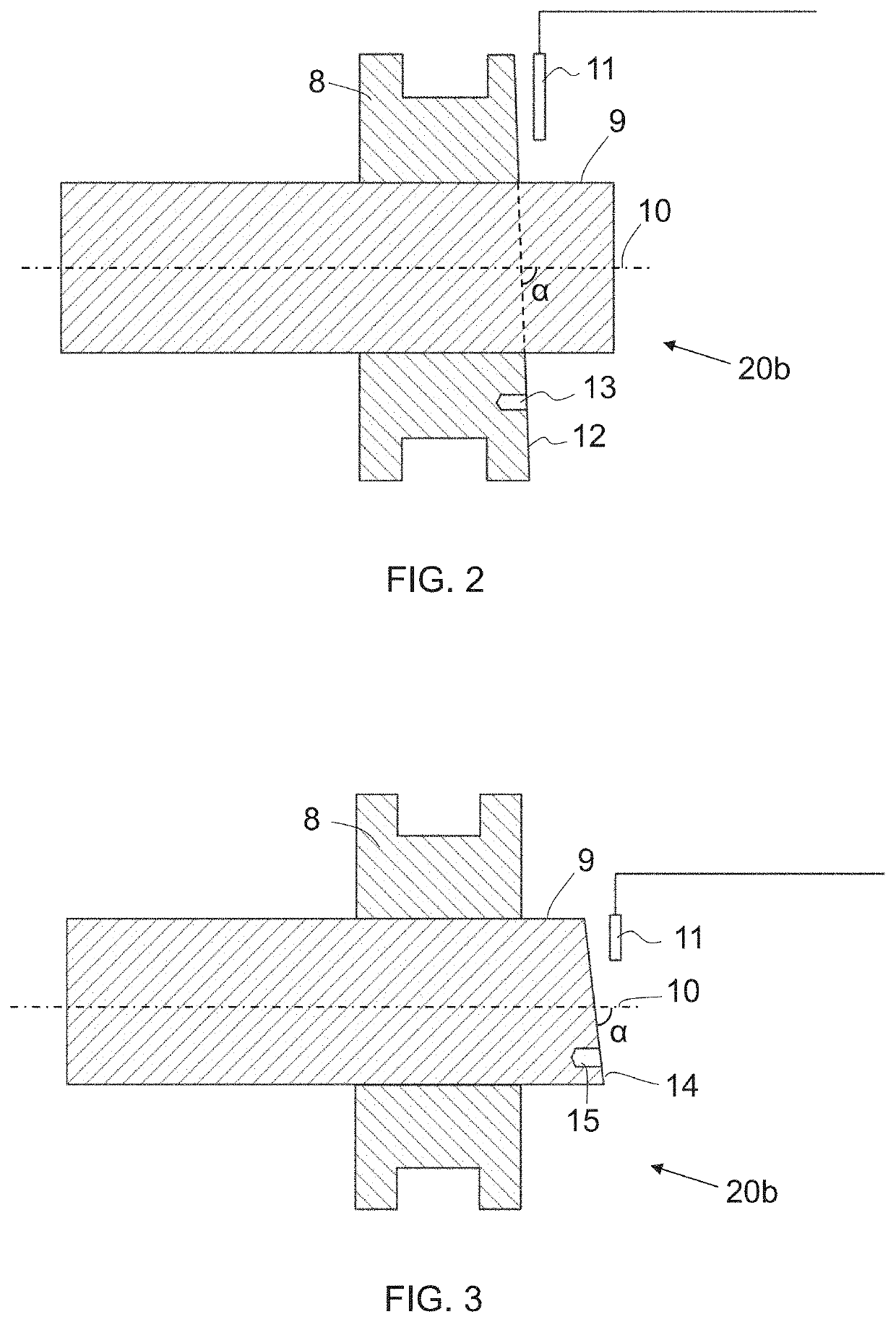
[0037]FIG. 2 shows a measurement arrangement 20b according to the invention. In the embodiment of FIG. 2, the rotatable component is a pulley 8 of a counterweight. The pulley 8 is arranged around an axle 9. The pulley 8 is configured to be rotatable about a rotation axis 10. The axle 9 can be supported by means of at least one bearing and the pulley 8 can rotate with the axle 9. Alternatively, the axle 9 can be stationary and the pulley 8 can rotate around the axle 9. The pulley 8 could thus be supported by means of a bearing arranged on the axle 9.
[0038]The measurement arrangement is provided with an inductive sensor 11. In the embodiment of FIG. 2, the inductive sensor 11 is arranged adjacent to the pulley 8. One side surface 12 of the pulley 8 is configured so that the distance from the surface 12 to the inductive sensor 11 depends on the angular position of the pulley 8. The side surface 12 is arranged in respect of the rotation axis 10 of the pulley 8 at an angle a which differ...
second embodiment
[0040]FIG. 3 shows a measurement arrangement 20b according to the invention. In the embodiment of FIG. 3, the pulley 8 is supported by a rotatable axle 9. The axle 9 is thus supported by means of at least one bearing (not shown). The pulley 8 is attached to the axle 9 in a rotationally fixed manner. The rotation speed of the pulley 8 thus equals the rotation speed of the axle 9. Also the arrangement of FIG. 3 comprises an inductive sensor 11. The inductive sensor 11 is arranged to monitor the distance to an end surface 14 of the axle 9. In a similar way as in the embodiment of FIG. 2, the end surface 14 of the axle 9 is arranged in respect of the rotation axis 10 of the pulley 8 at an angle a which differs from 90 degrees. The angle a between the rotation axis 10 and the surface 14 can be, for instance, 80-89 degrees. In the embodiment of FIG. 3, the axle 9 is provided with a drilling 15 for balancing the axle 9. In the embodiment of FIG. 3, the drilling extends inwards from the end...
third embodiment
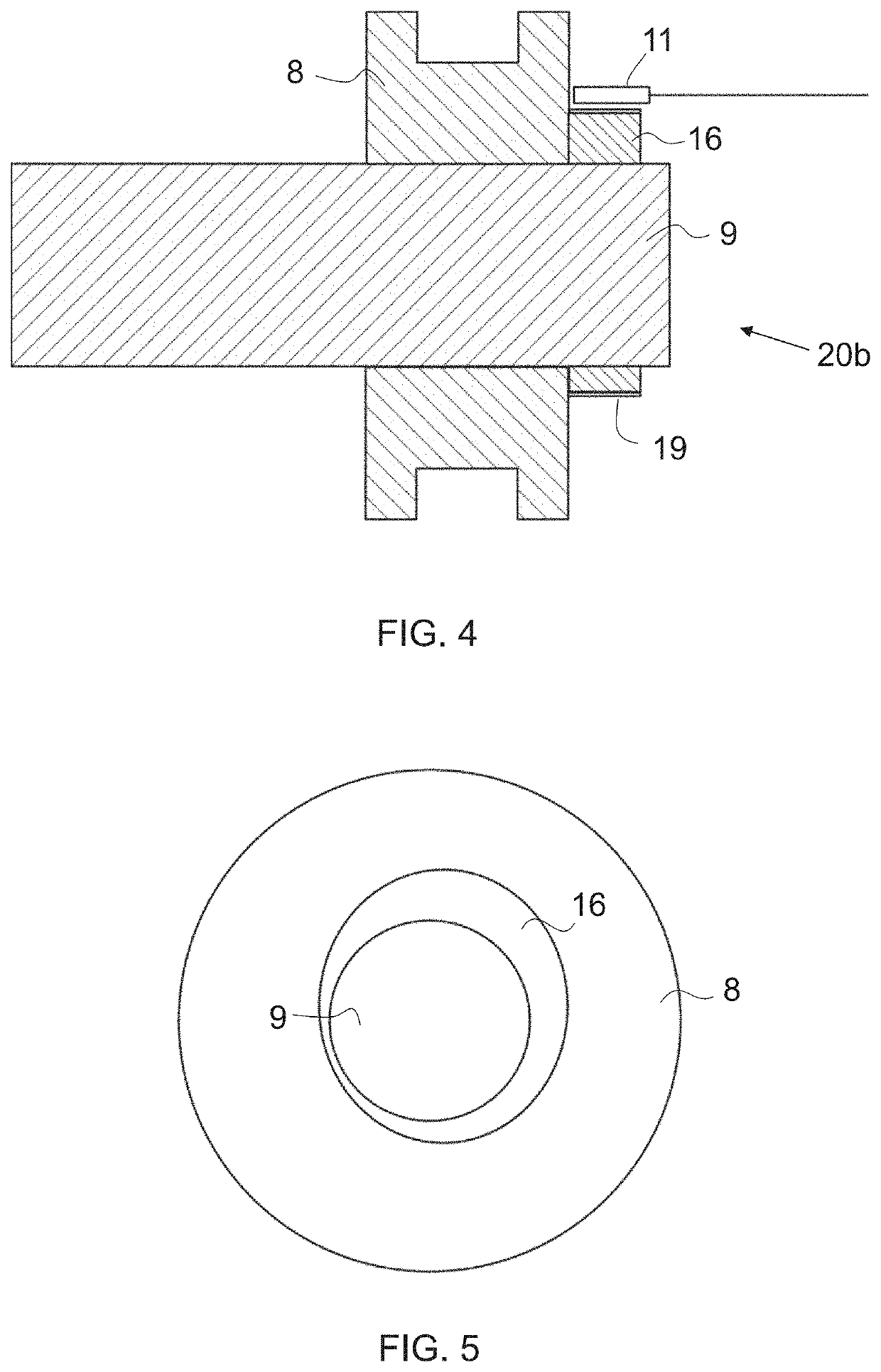
[0041]FIG. 4 shows a measurement arrangement 20b according to the invention. FIG. 5 shows an end view of the arrangement of FIG. 4 (inductive sensor not shown). In the arrangement of FIGS. 4 and 5, an assembly comprising a pulley 8 and an axle 9 is provided with a separate measurement part 16, which is utilized in determination of the rotation speed of the pulley 8. In the embodiment of FIGS. 4 and 5, the pulley 8 is attached in a rotationally fixed manner to the axle 9. The measurement part 16 is attached in a rotationally fixed manner to the axle 9. If the pulley 8 rotated relative to the axle 9, the measurement part 16 would be attached in a rotationally fixed manner to the pulley 8. The arrangement is provided with an inductive sensor 11 which is arranged to monitor the distance to the outer perimeter 19 of the measurement part 16. The measurement part 16 is arranged around the axle 9 and it has a non-circular shape. The thickness of the measurement part 16 thus varies. As the a...
PUM
 Abstract
Description
Claims
Application Information
 - R&D
- Intellectual Property
- Life Sciences
- Materials
- Tech Scout
- Unparalleled Data Quality
- Higher Quality Content
- 60% Fewer Hallucinations
Browse by: Latest US Patents, China's latest patents, Technical Efficacy Thesaurus, Application Domain, Technology Topic, Popular Technical Reports.
© 2025 PatSnap. All rights reserved.Legal|Privacy policy|Modern Slavery Act Transparency Statement|Sitemap|About US| Contact US: help@patsnap.com


