Fractal heat transfer device

Pending Publication Date: 2022-04-21
FRACTAL HEATSINK TECH
View PDF0 Cites 1 Cited by
  • Summary
  • Abstract
  • Description
  • Claims
  • Application Information

AI Technical Summary

Benefits of technology

The patent text describes a heatsink with fractal structures that can effectively cool a solid by reducing acoustic resonance and facilitating heat transfer. The fractal design also creates multiple pockets of separated flow that can lead to self-sustaining oscillations and acoustic resonance, which further improves heat transfer. The invention also involves a method of cooling a solid using the fractal heatsink. Overall, the fractal structure enhances the heatsinking process.

Problems solved by technology

Less than three recursions, and the fractal nature is not apparent, while present manufacturing technologies limit the manufacture of objects with a large range of feature scales.
Of course, due to limitations in the technology used to build these heatsinks, engineering compromise is expected.
However, a feature of an embodiment of the designs proposed herein is that vortices induced by fluid flow over a heat transfer surface will be chaotically distributed over various elements of the surface, thus disrupting the stagnant surface boundary layer and increasing the effective surface area available for heat transfer, while avoiding acoustic resonance which may be apparent from a regular array of structures which produce vortices and turbulence.

Method used


Image

  • Fractal heat transfer device
  • Fractal heat transfer device
  • Fractal heat transfer device

Examples


Embodiment Construction

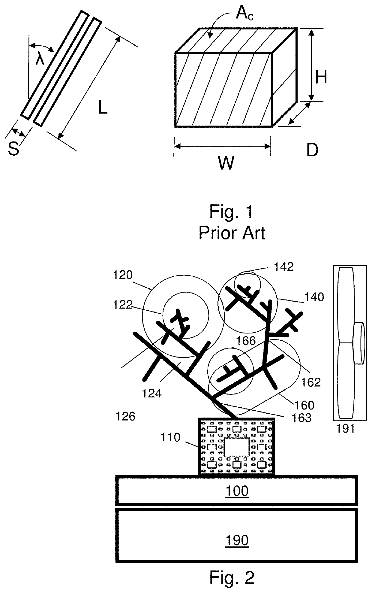
[0145]FIG. 2 illustrates a heatsink implementing a first embodiment of this invention. Note that the illustration is in two dimensions, but a three-dimensional embodiment is both possible and preferred. There is a heat transfer surface 100 that allows the heatsink to rest comfortably on a surface, such as the solid to be cooled 190. In the illustrated embodiment, the heat transfer surface 100 is roughly planar, having a closed Euclidian cross-section on the bottom. However, it might also have another shape, for example if the solid to be cooled does not have a planar face. A fractal-shaped heat exchange device begins at point 110. Note that the heatsink has three branches leaving from point 110—branch 120, branch 140, and branch 160. Also note that the branch structure initiating from point 110 is nearly identical to that at point 122 and 142, even though only point 110 is a true starting point. Thus, the fractal property of self-similarity is present. We call the structure that beg...


PUM


Abstract

A heatsink comprising a heat exchange device having a plurality of heat exchange elements each having a surface boundary with respect to a heat transfer fluid, having successive elements or regions varying according to a fractal relationship. According to one embodiment, a noise spectrum due to fluid flow is wideband. According to another embodiment, surface boundary layers are disrupted to increase heat transfer. Flow-induced vortices may be generated at non-corresponding locations of the plurality of fractally varying heat exchange elements.

Description

CROSS REFERENCE TO RELATED APPLICATIONS[0001]The present application is a:[0002]Continuation of U.S. patent application Ser. No. 16 / 056,481, filed Aug. 6, 2018, now U.S. Pat. No. 11,209,220, issued Dec. 28, 2021, which is a[0003]Continuation of U.S. patent application Ser. No. 14 / 984,756, filed Dec. 30, 2015, now U.S. Pat. No. 10,041,745, issued Aug. 7, 2018, which is a[0004]Continuation in part of U.S. patent application Ser. No. 14 / 817,962, filed Aug. 4, 2015, now U.S. Patent No. pending, and is a[0005]Continuation in part of U.S. patent application Ser. No. 13 / 106,640, filed May 12, 2011, now U.S. Pat. No. 9,228,785, issued Jan. 5, 2016, from which PCT / IB11 / 01026, filed May 13, 2011 claims priority, which is a[0006]Non-provisional of, and claims benefit of priority from, U.S. Provisional Patent Application No. 61 / 331,103, filed May 4, 2010, and[0007]the entirety of which are expressly incorporated herein by reference.FIELD OF THE INVENTION[0008]This invention relates to the field...

Claims


Application Information

Patent Timeline
IPC IPC(8): F28F1/40F28F21/02H01L23/36H01L23/367
CPCF28F1/40F28F21/02F28D2021/0029H01L23/367F28F2255/20H01L23/36F28F2215/10
Inventor POLTORAK, ALEXANDER I
Owner FRACTAL HEATSINK TECH
Why Eureka
Try Eureka