Fractal heat transfer device

a heat transfer device and fractal technology, applied in the field of heatsinks or items, can solve the problems of affecting the production efficiency of heatsinks, and limiting the manufacture of objects with a large range of feature scales, so as to reduce the narrow band acoustic resonance, reduce flow rate, and improve heat transfer efficiency

Active Publication Date: 2017-04-06
FRACTAL HEATSINK TECH
View PDF6 Cites 19 Cited by
  • Summary
  • Abstract
  • Description
  • Claims
  • Application Information

AI Technical Summary

Benefits of technology

[0086]In one embodiment, the heatsink comprises a heat exchange device with a plurality of heat exchange elements having a fractal variation therebetween. A heat transfer fluid, such as air, water, or another gas or liquid, is induced to flow through the heat exchange device. The heat transfer fluid has turbulent portions. The fractal variation in the plurality of heat exchange elements substantially reduces the narrow band acoustic resonance resulting from fluid flow around the heatsink elements as compared to a heatsink having a linear or Euclidian geometric variation between the plurality heat exchange elements. The turbulent flow also disturbs the stagnant surface boundary layer, leading to more efficient heat transfer, but generally reduced flow rates for the same motive force. Note that, since turbulence dissipates energy, under some conditions, the heat added to the system by inducing the heat transfer fluid flow can be a significant factor.
[0087]When a heat transfer fluid (air, gas or liquid) is induced to flow over a surface, there may be turbulence in the fluid. The fractal shape of the heatsink would generally provide a range of physical size parameters, and thus for any given flow rate, would typically induce turbulent flow over some portion of a fractal geometry array. Notably, because the flow for a given heatsink may vary over a range of speeds, and the temperature and viscosity of the fluid varies over a range of conditions, a fractal geometry facilitates optimization over a range of parameters.

Problems solved by technology

Less than three recursions, and the fractal nature is not apparent, while present manufacturing technologies limit the manufacture of objects with a large range of feature scales.
Of course, due to limitations in the technology used to build these heatsinks, engineering compromise is expected.
However a feature of an embodiment of the designs proposed herein is that vortices induced by fluid flow over a heat transfer surface will be chaotically distributed over various elements of the surface, thus disrupting the stagnant surface boundary layer and increasing the effective surface area available for heat transfer, while avoiding acoustic resonance which may be apparent from a regular array of structures which produce vortices and turbulence.

Method used


Image

  • Fractal heat transfer device
  • Fractal heat transfer device
  • Fractal heat transfer device

Examples


Embodiment Construction

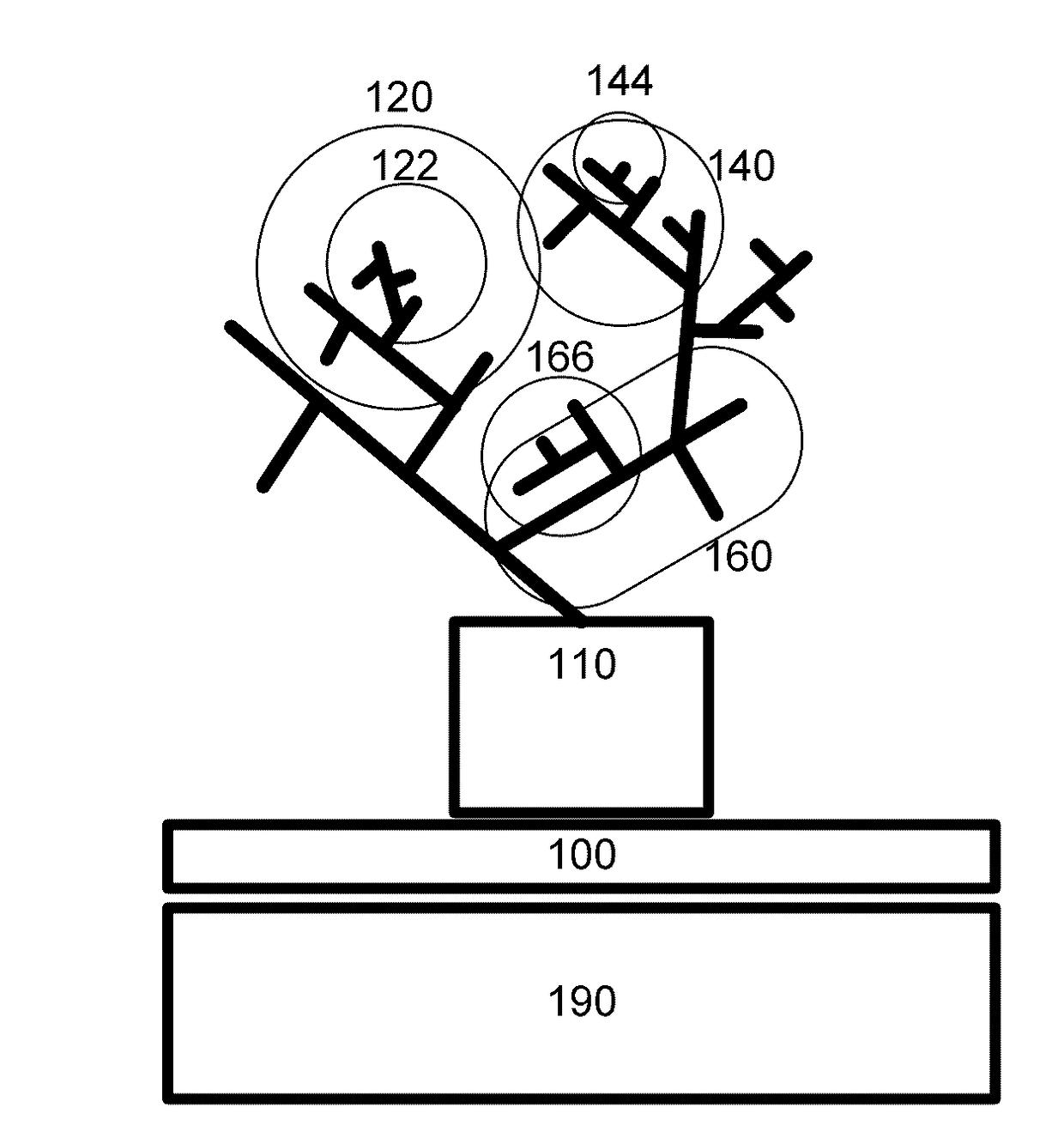
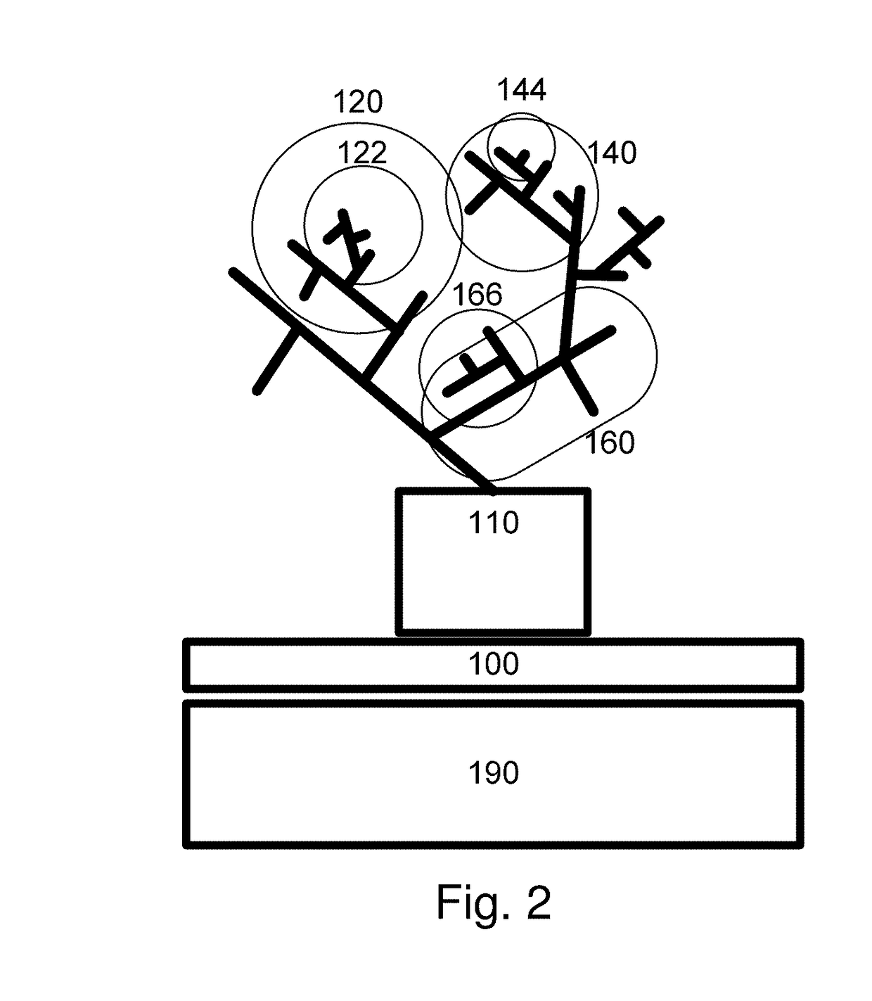
[0126]FIG. 2 illustrates a heatsink implementing a first embodiment of this invention. Note that the illustration is in two dimensions, but a three dimensional embodiment is both possible and preferred. There is a heat transfer surface 100 that allows the heatsink to rest comfortably on a surface, such as the solid to be cooled 190. In the illustrated embodiment, the heat transfer surface 100 is roughly planar, having a closed Euclidian cross-section on the bottom. However, it might also have another shape, for example if the solid to be cooled does not have a planar face. A fractal-shaped heat exchange device begins at point 110. Note that the heatsink has three branches leaving from point 110-branch 120, branch 140, and branch 160. Also note that the branch structure initiating from point 110 is nearly identical to that at point 122 and 142, even though only point 110 is a true starting point. Thus, the fractal property of self-similarity is present. We call the structure that beg...


PUM


Abstract

A heatsink comprising a heat exchange device having a plurality of heat exchange elements each having a surface boundary with respect to a heat transfer fluid, having successive elements or regions varying according to a fractal relationship. According to one embodiment, a noise spectrum due to fluid flow is wideband. According to another embodiment, surface boundary layers are disrupted to increase heat transfer. Flow-induced vortices may be generated at non-corresponding locations of the plurality of fractally varying heat exchange elements.

Description

CROSS REFERENCE TO RELATED APPLICATIONS[0001]The present application is a Continuation in part of U.S. patent application Ser. No. 14 / 817,962, filed Aug. 4, 2015, now pending, and U.S. patent application Ser. No. 13 / 106,640, filed May 12, 2011, now U.S. Pat. No. 9,228,785, issued Jan. 5, 2016, which is a non-provisional of, and claims benefit of priority from, U.S. Provisional Patent Application No. 61 / 331,103, filed May 4, 2010, and from which PCT / IB11 / 01026, filed May 13, 2011 claims priority, the entirety of which are expressly incorporated herein by reference.FIELD OF THE INVENTION[0002]This invention relates to the field of heatsinks or items that transfer heat between a concentrated source or sink and a fluid.BACKGROUND OF THE INVENTION[0003]A heat sink is a term for a component or assembly that transfers heat generated within a solid material to a fluid or gas medium, such as air or a liquid. A heat sink is typically designed to increase the surface area in contact with the c...

Claims


Application Information

Patent Timeline
Patent Type & Authority Applications(United States)
IPC IPC(8): F28F13/06F28D15/00
CPCF28D15/00F28F13/06F28F21/02F28D2021/0029F28F2215/10F28F2255/20H01L23/367F28F1/40H01L23/36
Inventor POLTORAK, ALEXANDER
Owner FRACTAL HEATSINK TECH
Why Eureka
Try Eureka