Methods for determining fluidic flow configurations in a pool system

a technology of fluid flow and pool system, applied in the direction of computer control, program control, instruments, etc., can solve the problems of unsatisfactory conditions and unsatisfactory conditions

Active Publication Date: 2022-04-28
POOLSIDE TECH LLC
View PDF0 Cites 5 Cited by
  • Summary
  • Abstract
  • Description
  • Claims
  • Application Information

AI Technical Summary

Benefits of technology

[0008]The one or more of the plurality of swimming pool components can include an actuator-based pool cleaner. The one or more of the plurality of swimming pool components can include a booster-pump-based pool cleaner.
[0009]The one or more potential configurations can include fluid flow through a spa basin.
[0010]The plurality of swimming pool components can further include a plurality of fluid flow pumps. The one or more conditions can be selected from the group consisting of: underflow, overflow, and safety conditions of the plurality of fluid flow pumps.
[0011]The one or more conditions can be selected from the group consisting of: underflow, overflow, and flow rate restrictions of the fluidic connections. The computer-implemented method can further include adjusting power output of at least one of the plurality of swimming pool system components based on the flow rate restrictions.
[0012]The plurality of swimming pool system components can include at least a pool basin and a spa basin. The one or more conditions can be selected from the group consisting of: underflow, overflow, and fluid spillover restrictions.
[0013]The plurality of swimming pool system components can include at least one or more fluid valves. The plurality of swimming pool system components can include at least one or more pool heaters, pool coolers, or a combination thereof. The plurality of swimming pool system components can include at least one or more water features.

Problems solved by technology

The computer-implemented method can further include restricting a user's ability to select the one or more potential configurations resulting in unsatisfactory conditions.
The restricting step can include presenting an alternative to a user request that would bring about the one or more potential configurations resulting in unsatisfactory conditions.

Method used


Image

  • Methods for determining fluidic flow configurations in a pool system
  • Methods for determining fluidic flow configurations in a pool system
  • Methods for determining fluidic flow configurations in a pool system

Examples


configuration example 1

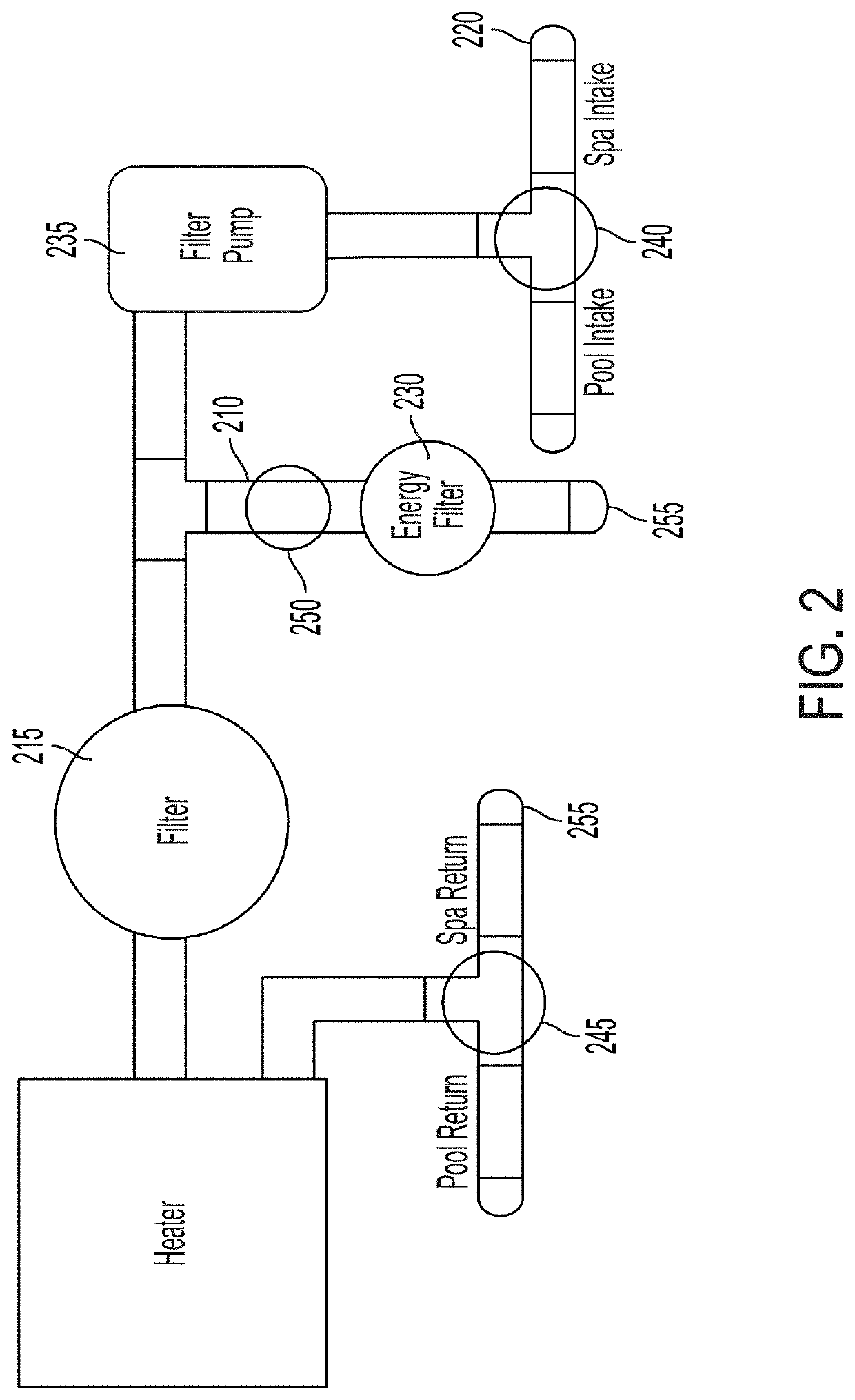
[0053]FIG. 2 depicts a pool system configuration according to an embodiment of the invention described herein. As shown, the pool cleaner line 210 is plumbed before the pool filter 215. In a scenario where both the pool cleaner and the spa are activated concurrently, both valves 240 and 245 can be configured to flow water from the spa intake 220 and to the spa return 225. However the valve 250 can also be open, leading water flow through the energy filter 230 and into the pool return 255. Thus, water can flow from the spa (e.g., via spa intake 220) and return to both the spa (e.g., via spa return 225) and the pool (e.g., through the energy filter 230). Eventually, the water level of the spa will reduce to a point where the spa is drained, since water intake is via the spa but water returns to the both the spa and the pool. In this scenario, the filter pump 235 will eventually run without fluid. The filter pump 235 can be damaged because no fluid is flowing through the plumbing intak...

configuration example 2

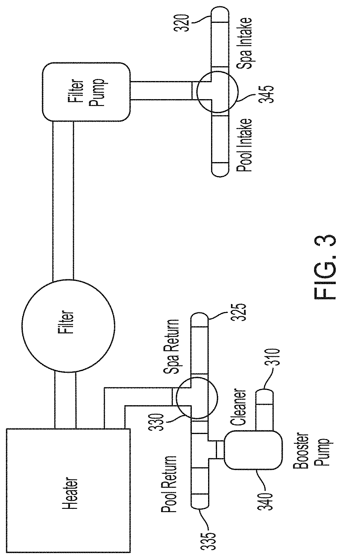
[0054]FIG. 3 depicts a pool system configuration according to an embodiment of the invention described herein. As shown, a booster pump 340 can activate for running a pool cleaner 310. In a similar scenario to Configuration Example 1, a scenario can arise where both the pool cleaner and the spa are activated concurrently. As the spa is activated, the valve 345 can be configured to flow water from the spa intake 320, and the valve 330 can be configured to flow to the spa return 325. However, as the cleaner 310 is also activated, the booster pump 340 can be activated as well. In this scenario, water can flow from the spa (e.g., via spa intake 320) and return to the spa (e.g., via spa return 325). As the valve 330 is configured for fluid flow for the spa (e.g., due to activation of the spa), the valve 330 can also concurrently be closed to fluid flow to the pool return 335 and the booster pump 310. Thus, the booster pump 310 in this scenario can operate without any suction fluid. This ...

configuration example 4

[0074]FIG. 5 depicts a pool system configuration according to an embodiment of the invention described herein. In this example, a pool pump 505 and spa pump 510 are each coupled to their own filter (e.g., pool filter 515 and spa filter 520, respectively). However, each pump shares a heater 525. While both pumps can filter water, only one can be connected to the heater 525 at any given time (e.g., due to the heater operating conditions). The control system can identify that both pumps 505 and 510 can operate at variable power output, speed, and the like. In this configuration, the control system can select a flowpath configuration that “shares” the heater 525 between the spa pump 510 and the main pump 505. For example, the heater 525 is coupled to the spa pump 510 for a period of time (e.g., by the control system switching valve 540 to direct water towards the heater and valve 530 to direct water toward the spa return), then the heater 525 is coupled to the main pump 505 for a non-ov...


PUM


Abstract

One aspect of the invention provides a computer-implemented method for controlling a swimming pool or spa system. The computer-implemented method includes: creating a data structure representing a plurality of swimming pool system components and fluidic connections between subsets of the plurality of swimming pool system components; receiving a request to control one or more of the plurality of swimming pool system components; calculating fluidic flows through the plurality of swimming pool system components based on one or more potential configurations of the plurality of swimming pool system components capable of fulfilling the request; and detecting whether the one or more potential configurations result in unsatisfactory conditions.

Description

CROSS-REFERENCE TO RELATED APPLICATION[0001]This application claims the benefit of priority under 35 U.S.C. § 119(e) to U.S. Provisional Patent Application Ser. No. 63 / 106,165, filed Oct. 27, 2020. The entire content of this application is hereby incorporated by reference herein.BACKGROUND OF THE INVENTION[0002]Pool systems (e.g., swimming pools, hot tubs, spas, and the like) typically include various types of maintenance components for heating, cooling, and / or cleaning the pool water, and water features for user enjoyment of the system, such as water fountains, waterfalls, pools, spas, and the like. The different components can be fluidically coupled to one another in a multitude of configurations. Further, conventional pool systems do not account for the variety of different fluid configurations, or the different energy, flow rate, or other operating conditions of the components during water flow activities.SUMMARY OF THE INVENTION[0003]One aspect of the invention provides a compu...

Claims


Application Information

Patent Timeline
Patent Type & Authority Applications(United States)
IPC IPC(8): A61H33/00G05B15/02
CPCA61H33/005G05B15/02A61H2201/5007A61H2201/02A61H2033/0058G05B2219/2642G05D7/0617E04H4/14E04H4/1245G05D11/003G05D11/132E04H4/129E04H4/1672
Inventor DOAN, WILLIAM R.REZNIK, STAN
Owner POOLSIDE TECH LLC
Why Eureka
Try Eureka