Method and a computer system for monitoring and controlling an HVAC system

a computer system and hvac technology, applied in space heating and ventilation control systems, lighting and heating apparatus, heating types, etc., can solve problems such as considerable logistical and technical complexity, and achieve the effect of improving the operation of a multi-zone hvac system

Pending Publication Date: 2022-04-28
BELIMO HOLDING AG
View PDF26 Cites 1 Cited by
  • Summary
  • Abstract
  • Description
  • Claims
  • Application Information

AI Technical Summary

Benefits of technology

[0003]It is an object of this invention to provide a computer-implemented method and a computer system for monitoring and controlling an HVAC system, which do not have at least some of the disadvantages of the prior art. In particular, it is an object of the present invention to provide a computer-implemented method and a computer system for monitoring and controlling a multi-zone HVAC system, which method and computer system make it possible to monitor and improve operation of a multi-zone HVAC system, without having to rely entirely on a building control system.
[0006]By grouping the operating variables and their associated devices into different sets, depending on the interdependencies between the temporal courses of the operating variables, a relationship is determined and defined between the measurable variables and contributing devices in an HVAC system. This makes it possible to determine which devices of the HVAC system belong together, e.g. they are connected to the same thermal energy source, without requiring a building control or automation system or having access to the data of a building control or automation system. Consequently, without the information from a building control or automation system, it is possible to not only monitor, analyze and control individual HVAC devices, such as pumps, ventilators, heaters, chillers, actuators, valves, dampers, radiators, heat exchangers, but also their interaction, interoperation, and interdependencies within the context and performance of the overall HVAC system. Therefore, operation and performance of a multi-zone HVAC system can be monitored, analysed and improved, without having to rely entirely on a building control system or a building automation system.

Problems solved by technology

Coordination of these various technical specialists at different stages and integration of building control systems and HVAC devices from different manufacturers cause considerable logistical and technical complexities, which often continue through the operational and maintenance life cycle of HVAC systems.

Method used


Image

  • Method and a computer system for monitoring and controlling an HVAC system
  • Method and a computer system for monitoring and controlling an HVAC system
  • Method and a computer system for monitoring and controlling an HVAC system

Examples


Embodiment Construction

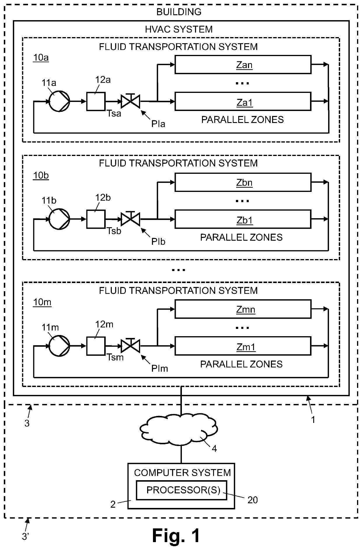
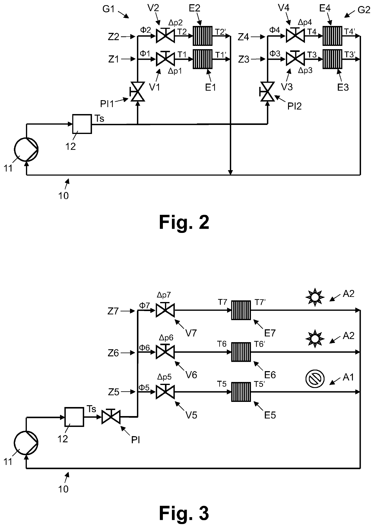
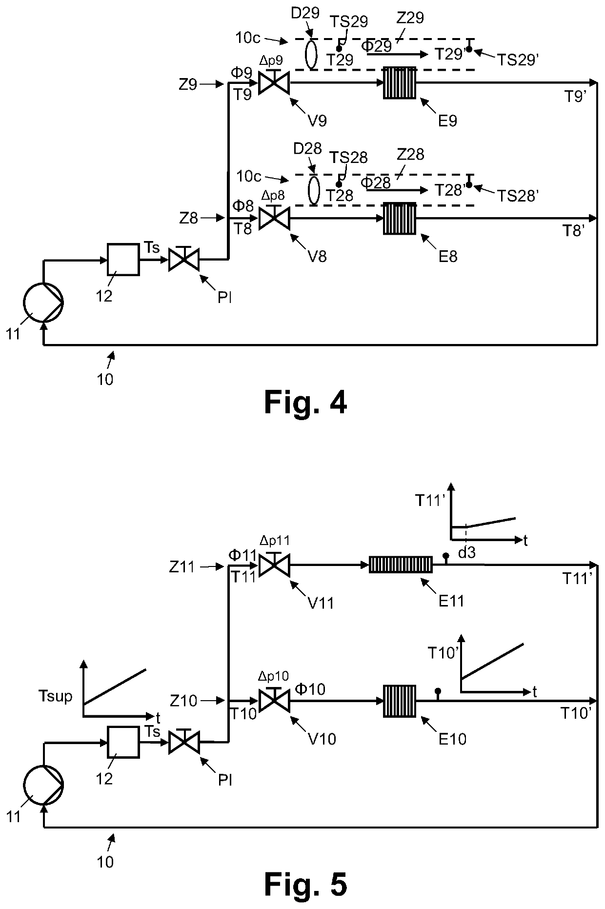
[0037]In FIG. 1, reference numeral 1 refers to an HVAC system arranged in a building 3, 3′ or in several buildings. As illustrated in FIG. 1, the HVAC system 1 comprises several fluid transportation systems 10a, 10b, 10m. Further examples of fluid transportation systems 10, 10c, which could be part of the HVAC system 1 illustrated in FIG. 1 or in another HVAC system, are illustrated in FIGS. 2, 3, 4, and 5. The fluid transportation systems 10, 10a, 10b, 10c, 10m comprise circuits with fluid transport lines, e.g. pipes for liquid fluids, such as water and / or glycol, or ducts for gaseous fluids, such as air. In the examples illustrated in FIGS. 1-5, the reference numerals 10, 10a, 10b, 10m refer to fluid transportation systems comprising pipes for transporting liquid fluids, e.g. water. In the example of FIG. 4, the reference numeral 10c refers to a fluid transportation system comprising ducts for transporting gaseous fluids, e.g. air.

[0038]As illustrated in FIGS. 1-5, the transportat...


PUM


Abstract

For monitoring and controlling an HVAC system which comprises one or more fluid transportation systems with a plurality of parallel zones, a plurality of operating variables of the fluid transportation systems are received (S1) from devices of the HVAC system. Temporal courses are determined (S3) for the operating variables. Interdependencies are determined (S4) between the temporal courses of the operating variables. Depending on the interdependencies, the operating variables and their associated devices are grouped (S5) into different sets which each relates to a different section of the HVAC system and includes the related operating variables and associated devices. The sets are used (S6) to control the devices of a particular section of the HVAC system and / or to generate a fault detection message regarding one or more of the devices of the particular section of the HVAC system.

Description

FIELD OF THE INVENTION[0001]The present invention relates to a method and a computer system for monitoring and controlling an HVAC (Heating, Ventilation, Air Conditioning and Cooling) system. Specifically, the present invention relates to a computer-implemented method and a computer system for monitoring and controlling an HVAC system which comprises one or more fluid transportation systems with a plurality of parallel zones in each of the fluid transportation systems.BACKGROUND OF THE INVENTION[0002]HVAC system for heating, ventilating, air conditioning and cooling one or more buildings comprise one or more fluid transportation systems for moving liquid or gaseous fluids to or through rooms or spaces of the buildings such as to distribute thermal energy. The fluid transportation systems comprise circuits with fluid transport lines, e.g. pipes for liquid fluids or ducts for gaseous fluids, and fluid transportation drivers, e.g. pumps for liquid fluids or ventilators for gaseous flui...

Claims


Application Information

Patent Timeline
Patent Type & Authority Applications(United States)
IPC IPC(8): F24F11/32F24F11/63
CPCF24F11/32F24F2140/20F24F11/63F24F2140/00
Inventor REIDER, FORESTMISCHLER, STEFAN
Owner BELIMO HOLDING AG
Why Eureka
Try Eureka